


Reelmaster 5010- H
Cutting Units
Page 7 - 21
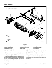
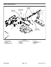
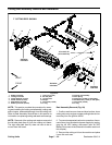
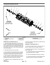
Removal (Fig. 27)
1. Remove lock nut (item 3), compression spring (item
2) and washer (item 12) from bedbar adjuster screw
(item 4).
2. Remove bedbar (see Bedbar Assembly in this sec-
tion).
NOTE: Insidethreads inbedbaradjustershaft (item10)
are left- hand threads.
3. Unscrew bedbar adjuster screw (item 4) from the
bedbar adjuster shaft (item 10).
4. Remove bedbar adjuster shaft (item 10) from cutting
unit frame:
A. Remove lock nut and flat washer from adjuster
shaft.
B. Slide adjuster shaft and wave washer from cut-
ting unit frame.
5. Inspect keyed flangebushings (item 5) in cutting unit
frame and remove if necessary.
6. If detent (item 7) is damaged, remove it from cutting
unit side plate by removing the cap screw (item 6).
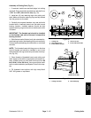
Installation (Fig. 27)
1. If detent (item 7) was removed, secure detent to cut-
ting unit side plate with cap screw. Torque cap s crew
from 14 to 16 ft- lb (19 to 21 N- m).
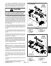
2. If keyed flangebushings (item 5)were removed from
cutting unit frame, apply antiseize lubrication to bushing
bore in cutting u nit frame. Align key on bushing to slot in
frame and slide bushing into frame.
3. Install bedbar adjuster shaft (item 10) to cutting unit
frame:
A. Slide wave washer onto bedbar adjuster shaft
andthenslideadjustershaftintokeyedflangebush-
ing in cutting unit frame.
B. Secure adjuster shaft with flat washer and lock
nut.Tightenlock nutto shoulder ofadjuster shaftand
then torque lock nut from 15 to 20 ft- lb (21 to 27
N-m).
NOTE: Insidethreadsin bedbaradjustershaft(item 10)
are left- hand threads.
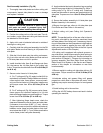
4. Apply antiseizelubricantto threadsof bedbaradjust-
er screw (item 4) that fit into bedbar adjuster shaft (item
10). Thread bedbar adjuster screw into adjuster shaft.
5. Install bedbar(see BedbarAssembly inthis section).
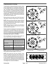
6. Install washer (item12), compression spring (item2)
and lock nut (item 3) onto bedbar adjuster screw. Tight-
en the lock nut on each bedbar adjuster assembly until
thecompressionspringis fullycompressed, thenloosen
lock nut 1/2 turn.
7. Adjust cutting unit ( see Cutting Unit Operator’s
Manual).
Cutting
Units