


Reelmaster 5010- HGroomer Page 8 - 16
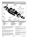
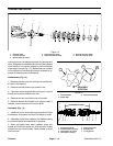
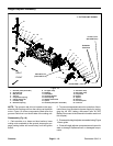
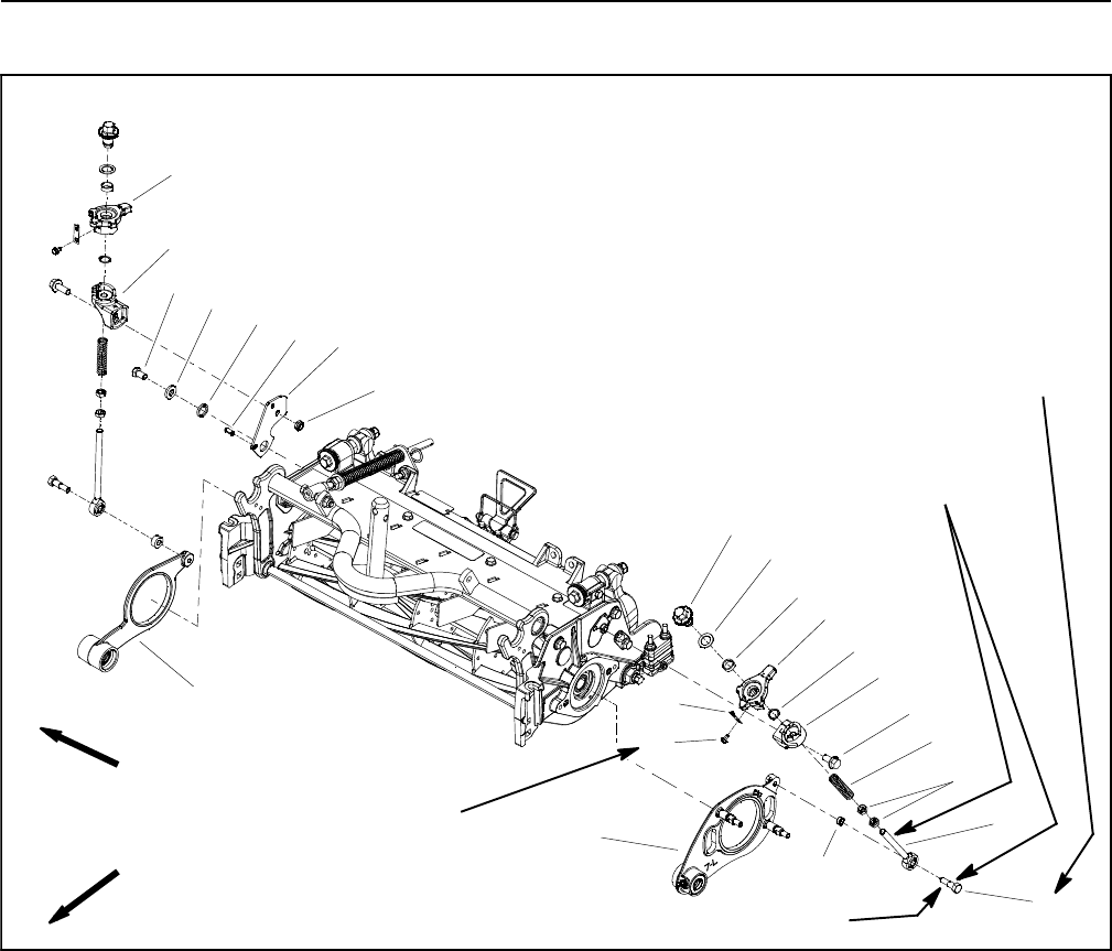
Height Adjuster Assembly
Figure 18
1. Groomer plate (drive side)
2. Shoulder bolt
3. Ball joint rod
4. Jam nut
5. Compression spring
6. Flange head screw
7. LH lower ramp
8. External snap ring
9. LH upper ramp
10. Bushing
11. Flat washer
12. Groomer adjuster
13. Detent spring
14. Washer head screw
15. Spacer
16. Groomer plate (non-drive side)
17. RH lower ramp
18. RH upper ramp
19. Cap screw
20. Spacer
21. Spacer
22. Roll pin
23. Groomer plate
24. Lock nut
30 to 40 in-lb
(3.4 to 4.5 N-m)
Antiseize
Lubricant
4
3
1
2
9
10
11
8
5
6
7
12
13
14
17 to 21 ft-lb
(23to28N-m)
15
16
17
18
19
20
21
22
23
24
FRONT
RIGHT
7” CUTTING UNIT SHOWN
Loctite #242
NOTE: The groomer reel drive is located on the oppo-
site sideof the cuttingunit from thecutting reelh ydraulic
motor. Figure 18 shows components used when the
groomer reel drive is on the left side of the cutting unit.
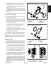
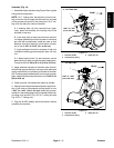
Disassembly (Fig. 18)
1. Parkmachineonacleanand level surface, lower
cutting units completely to the ground, stop engine, en-
gage parking brake and remove key from the ignition
switch.
2. To preventunexpected reel motor operation,discon-
nect motors from the electrical power supply by unplug-
ging the 48 VDC battery disconnect (see 48 VDC
BatteryDisconnectin theGeneralInformation sectionof
this chapter).
3. Disassembleheight adjusterasneeded usingFigure
18 as a guide.
4. Clean allheight adjustercomponents andinspect for
wear or damage. Replace all worn or damaged compo-
nents.