


Reelmaster 5010- H Hydraulic SystemPage 4 - 75
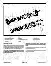
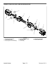
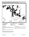
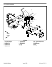
Removal (Fig. 65)
1. Park the machine on a level surface, lower the cut-
ting units and stop the engine. Remove the key from the
ignition switch.
2. Chock rear wheels to prevent machine from moving
or shifting.
3. Read the General Precautions for Removing and
Installing Hydraulic System Components at the begin-
ning of the Service and Repairs section of this chapter.
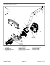
4. Remove front wheel, brake drum, wheel hub and
brake assemblyfrom machine (see Brake Service inthe
Service and Repairs section of Chapter 6 - Chassis).
CAUTION
Before opening hydraulic system, operate all hy-
draulic controls to relieve system pressure and
avoid injury from pressurized hydraulic oil. See
Relieving HydraulicSystem Pressurein the Gen-
eral Information section of this chapter.
5. Thoroughly clean hydraulic tube ends and fittings on
wheelmotor toprevent hydraulicsystem contamination.
6. Label hydraulic connections at wheel motor for as-
sembly purposes.
7. Disconnect hydraulic tubes from fittings on wheel
motor. Allow tubes to drain into a suitable container.
8. Put caps o r plugs on disconnected tubes and fittings
to prevent contamination.
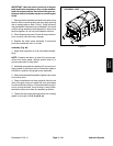
NOTE: Right and left front wheel motors are the same
basic design with some minor differences. The left side
wheel m otor can be identified by the machined groove
on the end of the output shaft. If both motors are r e-
moved from the machine, label motors for assembly
purposes.
9. Support wheel motor to prevent it from falling. Re-
move four(4) lock nutsfrom cap screws that securemo-
tor and brake adapter to frame.
10.Note location of spring clip (item 17) for assembly
purposes. Remove four (4) cap screws and brake
adapter from wheel motor and frame.
11.Remove wheel motor from machine.
12.If hydraulicfittingsare toberemoved from wheelmo-
tor, mark fitting orientation to allow correct assembly.
Remove fittings from motor and discard O- rings.
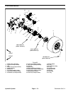
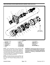
Installation (Fig. 65)
1. If fittings were removed from wheel motor, lubricate
and place new O- rings to fittings. Install fittings into mo-
tor ports using marks made during the removal process
to properlyorientate fittings(see HydraulicFitting Instal-
lationin theGeneral Information section ofthischapter).
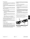
2. Position wheelmotor and brake adapter toframe. In-
stall spring clip (item 17) and four (4) cap screws to
wheel motora nd frame. Make surethat spring clip ispo -
sitioned as noted during d isassembly.
3. Install and tighten four (4) lock nuts onto cap screws
to secure motor and brake bracket to frame. Torque lock
nuts from 80 to 100 ft- lb (109 to 135 N-m).
4. Remove caps and plugs from disconnected hydrau-
lic tubes and fittings.
5. Lubricate and position new O- rings to fittings on
wheel motor. Use labels placed during the removal pro-
cess to properly install and secure hydraulic tubes to
wheel motor fittings (see Hydraulic Hose and Tube In-
stallationinthe GeneralInformations ectionof thischap-
ter)
6. Install brake assembly, wheel hub, brake drum and
frontwheelto machine(seeBrake ServiceintheService
and Repairs section of Chapter 6 - Chassis).
7. Make sure that wheel hub lock nut (item 12) is tight-
enedfrom 315to385ft-lb(428to522N-m)and wheel
lug nuts are tightened from 70 to 90 ft-lb (95 to 122
N-m).
8. Check and adjust oil level in hydraulic reservoir.
IMPORTANT: Ifawheel motorfailure occurred,refer
to Traction Circuit Component Failure in the Gener-
al Information section for information regarding the
importance of removing contamination from the
traction circuit.
9. Operate machine functions slowly until air is out of
system (see Charge Hydraulic System in this section).
Hydraulic
System