


Reelmaster 5010- H Hydraulic SystemPage 4 - 13
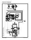
Traction Circuit
The hydraulic traction circuit consists of a variable dis-
placementpiston pump(P3) connectedin aclosed loop,
parallelcircuitto two(2) orbitalrollervane wheelmotors.
The piston (traction) pump input shaft is rotated by a
drive shaft connected to the motor/generator shaft that
is driven by the engine flywheel.
Traction circuit pressure (forward and reverse) can be
measured at test ports located in the hydraulic tubes
that connect the front wheel motors.
NOTE: In high load traction situations, the 48 VDC mo-
tor/generator may automatically assist the engine to
maintain piston (traction) pump input speed.
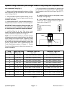
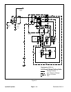
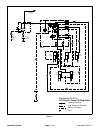
Forward Direction (Fig. 11)
Pushing the top of the traction pedal angles the piston
(traction) pump swash plate to create a flow of oil. This
oil flow is directed to the wheel motors via hydraulic
hosesand tubesto drive thewheels intheforward direc-
tion. Forward traction pressure is limited to 3625 PSI
(250bar) bythe forwardtraction reliefvalve (R3)located
in the piston (traction) pump.
Oil flowing from the wheel motors returns to the variable
displacement pump and is continuously pumped
through the traction circuit as long as the traction pedal
is pushed.
The angle of the swashplate determines pumpflow and
ultimately traction speed. When the traction pedal is de-
presseda smallamount,a smallswash platerotationre-
sults inlowpump outputand lowertractionspeed.When
the traction pedal is depressed fully, the pump swash
plate rotates fully to provide maximum pump output and
traction speed.
Gear pumpsection (P2) suppliesoil flow forthe steering
circuit and also provides a constant supply of charge oil
totheclosedlooptractioncircuit. This charge oil pro-
videslubricationfortractioncircuitcomponentsand also
replenishes traction circuit oil that is lost due to internal
leakage in the traction circuit.
The hydraulic reservoir provides fluid for the gear pump
(P2) through the suction hose. Charge pump flow is di-
rected to the low pressure side of the closed loop trac-
tion circuit. Charge pressure is limited by the charge
relief valve (R5) located in the piston (traction) pump.
Thechargereliefpressureis200PSI(14bar).
The piston pump (P3) includes a flushing valve that
bleeds off a small amount of hydraulic fluid for cooling
of theclosed loop traction circuit. The chargesystem re-
plenishes oil that is bled from the traction circuit by the
flushing valve.
Reverse Direction
The traction circuit operates essentially the same in re-
verse as it does in the forward direction. However, t he
flow through the circuit is reversed. Pushing the bottom
of the traction pedal rotates the piston (traction) pump
swash plate to create a flow of oil. This oil is directed to
the wheel motors to drive the wheels in the reverse
direction. Reverse traction pressure is limited to 3625
PSI (250 bar) by the reverse traction relief valve (R4) lo-
cated in the piston (traction) pump.
Oil flowing from the wheel motors returns to the piston
(traction)pump andis continuouslypumped throughthe
closed loop traction circuit as long as the traction pedal
is pushed.
The charge circuit and flushing valve function the same
in reverse as they do in the forward direction.
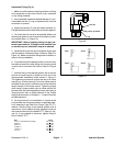
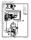
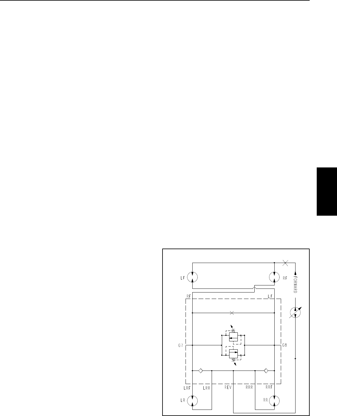
CrossTrax
TM
AWD (Optional)
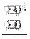
On machines equipped with the optional CrossTrax
TM
AWDkit, four(4) wheelmotorsare used (Fig.12).Piston
(traction) pump flow is directed to the front tires and the
opposite rear tires to maximize traction. To reduce tire
scuffing when turning, traction system pressure is
equalized in the AWD manifold with an orifice and a bi-
directional relief valve. Check valves in the AWD man-
ifold allow the rear wheel motors to over run during tight
turns.
Figure 12
G5
CrossTrax AWD Hydraulic Schematic
TM
Hydraulic
System