


Reelmaster 5010- HPage 5 - 68Electrical System
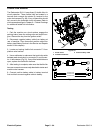
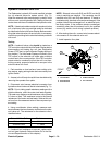
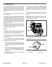
Cutting Reel Motor
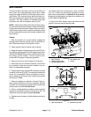
The five (5) cutting reel motors are identical 48 VDC,
brushless, permanent magnet motors. Each motor has
its ownintegral invertor and on- board controller.The In-
foCenter Display can be used to monitor the speed and
current draw for the five (5) cutting unit motors during
machine operation. Also, if a p roblem exists with any
cutting reel motor, a fault may have occurred that would
be indicated by a fault code on the InfoCenter Display.
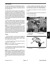
Because thecutting reelmotors usedon theReelmaster
5010- H are the same motors,motors from different cut-
ting units can be exchanged. If the problem follows a
motor to the new cutting unit, the motor is likely the is-
sue. If the problem remains with the cutting unit, the is-
sue is likely due to the cutting unit or electrical
components or wiring to that cutting unit.
NOTE: Before considering that cutting reel motor ser-
vice work is necessary, check for any existing fault
codes that indicate problems with a reel motor (see
Fault Codesin the Troubleshooting sectionof this chap-
ter). If acutting reel motor isfaulty, there will likelybe nu-
merous fault codes that are listed b y the InfoCenter
display.
Testing
1. Park machine on level surface, lower cutting units,
stop engine, apply parking brake and remove key from
ignition switch.
2. Separate system components from the 48 VDC bat-
tery pack by unplugging the 48 VDC battery disconnect
(see48VDC BatteryDisconnectinthe GeneralInforma-
tion section of this chapter). This will prevent unex-
pected cutting unit operation.
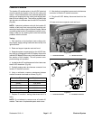
3. Locate cutting reel motor cable electrical connec-
tions atmachine wire harnessfor motor that isto betest-
ed.
IMPORTANT: When disconnecting reel motor cable
connectors, take care to not damage the cable or
connectors. The reel motor cable is not available as
a separate replacement part.
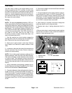
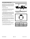
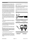
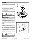
4. Carefully disconnect two (2) reel motor cable con-
nectors f rom machine wire harness (Fig. 68).
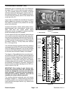
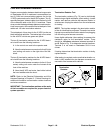
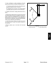
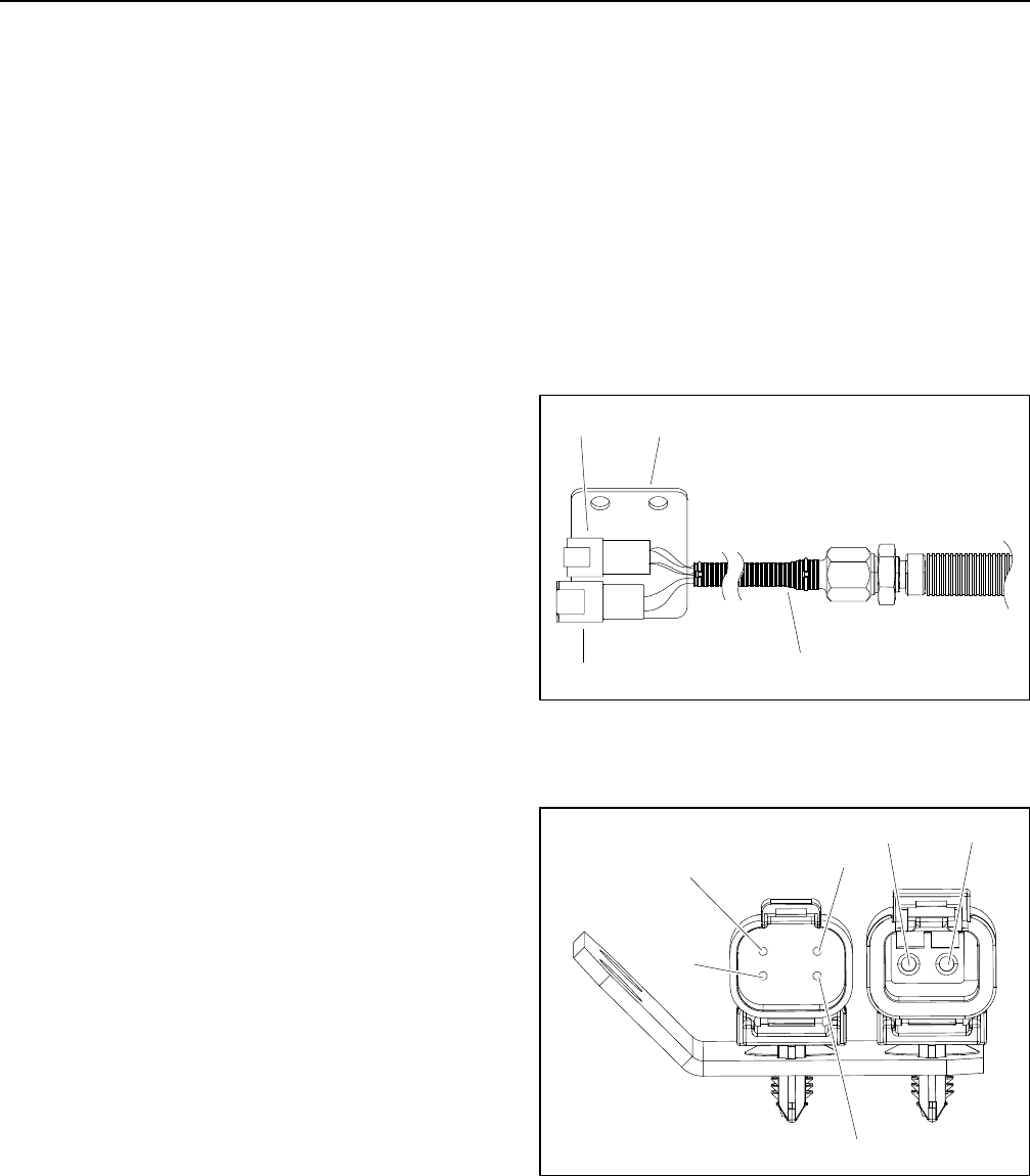
5. Using a multimeter, measure resistance between 48
VDCgroundterminal(black wire)inthe 2wire connector
and location ID terminal (blue wire) in 4 wire connector
(Fig. 69). Resistance should be approximately 18.8
K- ohms.
6. If measured resistance is incorrect, consider that the
cutting reel motor is faulty.
NOTE: If cutting reel motor removal, installation, disas-
sembly or assembly information is needed, see Cutting
Reel Motor and Cutting Reel Motor Service in the Ser-
vice and Repairs section of this chapter.
7. After testing is completed, secure two (2) reel motor
cable connectors to machine wire harness connectors.
8. Plug the 48 VDC battery disconnect back into the
socket.
1. Cable from motor
2. 4 wire connector
3. 2 wire connector
4. Connector plate
Figure 68
2
3
1
4
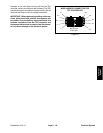
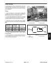
1. 48 VDC ground (black)
2. 48 VDC power (red)
3. Location ID (blue)
4. 48 VDC logic (white)
5. CAN-bus (green)
6. CAN-bus (yellow)
Figure 69
2
3
1
4
5
6