


Reelmaster 5010- H Hydraulic SystemPage 4 - 91
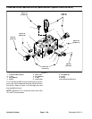
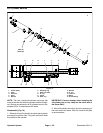
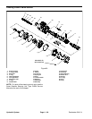
Removal (Fig. 75)
1. Park the machine on a level surface, engage the
parking brake, lower the cutting units and stop the en-
gine. Remove the key from the ignition switch.
2. To prevent unexpected cutting unit operation, dis-
connect the cutting units from the electrical power sup-
ply by unplugging the 48 VDC battery disconnect (see
48 VDC Battery Disconnect in the General Information
section of this chapter).
3. Read the General Precautions for Removing and
Installing Hydraulic System Components at the begin-
ning of the Service and Repairs section of this chapter.
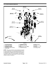
4. Label all hydraulic connections f or assembly pur-
poses. Thoroughly clean hydraulic connections prior to
loosening hydraulic lines from lift cylinder.
5. If lift cylinder for outside front cutting units (#4 or #5)
isbeing removed,remove flangenutand carriagescrew
that secure the hydraulic hose R - clamp to lift cylinder.
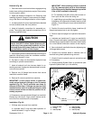
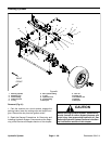
CAUTION
Before opening hydraulic system, operate all hy-
draulic controls to relieve system pressure and
avoid injury from pressurized hydraulic oil. See
Relieving HydraulicSystem Pressurein the Gen-
eral Information section of this chapter.
WA RNING
Make sure that cutting units are fully lowered be-
fore loosening hydraulic lines from lift cylinders.
If cutting units are not fully lowered as hydraulic
lines are loosened, the cutting units may drop
unexpectedly.
6. Disconnect hydraulic hoses from fittings in lift cylin-
derthatis toberemoved.Allowhosesto drainintoas uit-
able container. Remove and discard O- rings.
7. Put capsor plugs ondisconnected hosesand fittings
to prevent contamination.
8. Remove oneretainingring (item11)andthrustwash-
er (item 12) from the cylinder s lide pin (item 13) that se-
cures lift cylinder to lift arm. Pull slide pin from the lift
cylinder and lift arm. Locate and retrieve second thrust
washer.
9. Remove flange head screw (item 3) and flat washer
(item 5) that retain lift cylinder to cylinder pin.
10.Slide lift cylinder from cylinder pin and remove from
machine.
11.If hydraulic fittings are to be removed from lift cylin-
der, mark fitting orientation to allow correct assembly.
Remove fittings from lift cylinder and discard O- rings.
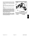
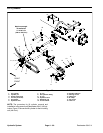
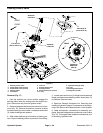
Installation (Fig. 75)
1. If hydraulicfittings wereremovedfrom liftcylinder,lu-
bricate new O- rings, position O- rings to fittings and
install fittingsinto lift cylinder ports(see Hydraulic Fitting
Installation in the General Information section of this
chapter). Make sure thatfittingsare orientated correctly.
2. Position lift cylinder to the frame with the barrel end
up.
3. Slide lift cylinder clevis onto cylinder pin.
4. Apply medium strength threadlocker to threads of
flange head screw (item 3). Secure cylinder with flange
head screw (item 3) and flat washer (item 5). Torque
screw from 77 to 93 ft-lb (105 to 126 N-m).
5. Align lift cylinder to lift arm mounting slot. Slide cylin-
der slide pin (item 13) with retaining ring (item 12) and
thrust washer (item 12) through the lift arm and lift cylin-
der. Install second thrust washer on pin and secure with
second retaining ring.
6. Remove caps and plugs from disconnected hoses
and fittings.
7. Coat new O - rings lightly with clean hydraulic oil,
install new O- rings and connect hydraulic hoses to fit-
tings on lift cylinder. Tighten hose connections (see Hy-
draulic Hose and Tube Installation in the General
Information section of this chapter).
8. Check oil level in hydraulic reservoir and add correct
oil if necessary.
9. Lubricate lift cylinder grease fittings.
10.Plug the cutting unit power disconnect connector
back in before operating the machine.
11.Follow hydraulic system start- up procedures (see
Hydraulic System Start- up in this section).
Hydraulic
System