


Reelmaster 5010- H Page 6 - 23 Chassis
IMPORTANT: When removing the seat suspension,
make sure to support the control arm to prevent
damage to the control arm electrical components
and control arm wiring harness.
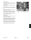
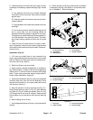
Removal (Figs. 18 and 19)
1. Park machine on a level surface, lower cutting units,
stop engine, engage parking brake and remove key
from the ignition switch.
2. Disconnect negative battery cable from 12 VDC bat-
tery (see 12 Volt Battery Service in the Service and Re-
pairs section of Chapter 5 - Electrical System).
3. Remove seat from machine(seeOperatorSeatin
this section).
IMPORTANT: Take care tonot damage the electrical
harness when removing seat suspension from ma-
chine.
4. Tilt and support seat frame to allow access to seat
suspension fasteners.
5. Support seat suspension t o prevent it from falling.
Remove four (4) flange head screws (item 8 in Figure
19)and flangenuts(item 5in Figure 19)that secureseat
suspension with attached seat brackets to seat base.
6. Remove seat suspension assembly from machine.
Locateand retrievefour (4)spacers(item 7in Figure19)
from between seat suspension assembly and seat
base.
7. Remove seat suspension components as needed
using Figures 18 and 19 as guides.
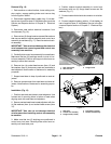
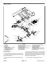
Installation (Figs. 18 and 19)
1. Install all removed seat suspension components us-
ingFigures18and19asguides.
A. Ifseat adjusters(items12or13 inFigure19)were
removedfromseatsuspension,installadjusterstuds
in rear set of holes in the suspension. Also, make
sure that washer (item 9 in Figure 19) is placed be-
tween seat adjuster and suspension.
IMPORTANT: Take care tonot damage the electrical
harness when installing seat suspension to ma-
chine.
2. Position seatbase cover and four (4) spacers (item
7 in Figure 19) to seat base.
3. Position seat suspension with attached seat brack-
ets to seat base. Use rear set of mounting holes in seat
brackets when aligning seat suspension assembly with
seat base.Securewith four(4)flangeheadscrews(item
8 in Figure 19) and flange nuts (item 5 in Figure 19).
4. Install seat to machine (see Operator Seat in this
section). Make sure to connect wire harness electrical
connector to the seat switch.
5. Connect negative battery cable to 12 VDC battery
(see 12 Volt Battery Service in the Service and Repairs
section of Chapter 5 - Electrical System).
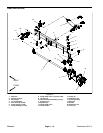
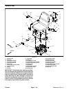
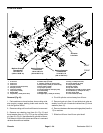
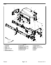
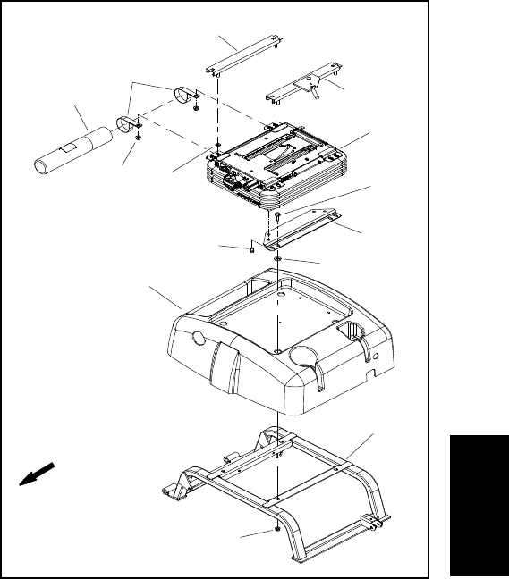
1. Seat suspension
2. Seat bracket (2 used)
3. Screw (4 used)
4. Seat base
5. Flange nut (8 used)
6. Seatbase cover
7. Spacer (4 used)
8. Flange screw (4 used)
9. Flat washer (4 used)
10. Manual tube
11. R- clamp (2 used)
12. Seat adjuster
13. Seat adjuster w/latch
Figure 19
1
2
4
3
5
6
7
8
FRONT
5
9
10
11
12
13
Chassis