


Reelmaster 5010- HPage 5 - 56Electrical System
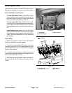
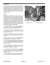
Joystick Raise and Lower Switches
Two(2) microswitchesfor thejoystickarelocatedon the
lower mow/raiselever thatisattachedtothe controlarm.
The rear switch on the control is used to lower (and en-
gage) the cutting units and the front switch to raise (and
disengage) them. A normally open contact in the switch
closes when the joystick is positioned to either lower or
raisethe cuttingunits.Each switchhasan electricalcon-
nector to make sure the normally closed contact on the
switch is not used. The raise switch has pink/blue and
blackh arness wiresconnected to itand thelower switch
has orange/whiteand black harness wiresconnected to
it. TheToro ElectronicController (TEC) monitors theop-
eration o f the joystick switches.
NOTE: Toraise orlower thedecksections, theoperator
seat has to be occupied. Also, to lower the cutting deck
sections, the traction speed h as to be in LOW (mow)
range.
Testing
NOTE: Before disconnecting the joystick switches for
testing, the switches and their circuit wiring should be
tested as a TEC controller input with the InfoCenter Dis-
play (see Diagnostics Screen (Cutting Units item) in the
InfoCenterDisplay inthis chapter). Ifthe InfoCenter Dis-
play verifies that the joystick switches and circuit wiring
arefunctioningcorrectly,no furtherswitch testingisnec-
essary. If the InfoCenter Display determines that either
joystick switchand circuitwiring are notfunctioning cor-
rectly, proceed with testing procedure
1. Park the machine on a level surface, engage the
parking brake, lower the cutting units and stop the en-
gine. Remove the key from the ignition switch.
2. Remove control arm covers to gain access to joys-
tick switches (see Control Arm in the Service and Re-
pairs section of Chapter 6 - Chassis).
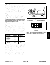
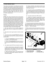
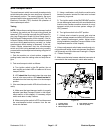
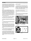
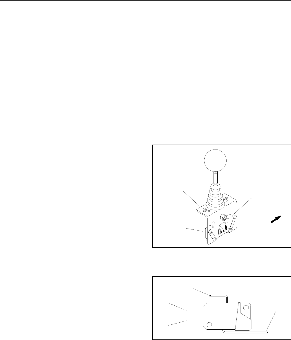
3. Disconnect wire harness electrical connector from
theraiseorlowerswitchthatistobetested(Fig.47).
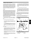
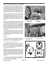
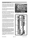
4. Connect a multimeter (ohms setting) across the nor-
mally open (NO) and common terminals of the switch
(Fig. 48).
5. With the joystick in the neutral (center) position,
there should be no continuity across the switch termi-
nals.
6. Move and hold the joystick to activate the switch be-
ing tested. There should be continuity across the switch
terminals.
7. If testing determines that joystick switch is faulty, re-
place switch.
8. If thejoystick switchtests correctlyand acircuit prob-
lem still exists, checkwire harness (see Electrical Sche-
matic and Circuit Drawings in Chapter 9 - Foldout
Drawings).
9. After switch testing is completed, connect wire har-
ness electrical connector to the joystick switch.
10.Install control arm covers to machine (see Control
Arm in the Service and Repairs section of Chapter 6 -
Chassis).
1. Lower mow/raise lever
2. Raise switch
3. Lower switch
Figure 47
FRONT
1
2
3
1. Common terminal
2. NO terminal
3. NC terminal
4. Switch lever
Figure 48
1
2
3
4