


Reelmaster 5010- HPage 5 - 58Electrical System
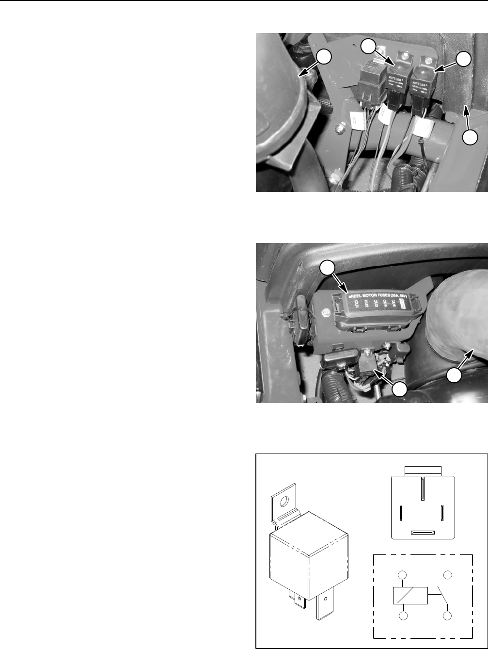
Main Power, Glow and 48 VDC Logic Relays
Your Reelmaster uses three (3) identical electrical re-
lays that have four (4) terminals. The main power and
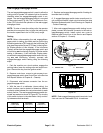
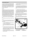
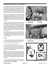
glow relays are attached to a frame bracket under the
hood near the engine exhaust muffler (Fig. 50). The 48
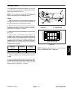
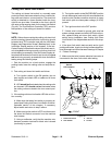
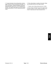
VDC logic relay is attached toa frame bracket underthe
hood behind the reel motor fuse block (Fig. 51). A tag
near the relay harness connector identifies each relay.
The main power relay is used to provide current to the
TEC controller, headlights, power point and optional
electric equipment. When the ignition switch is in the
ON/PREHEAT or START position, the main power relay
is energized. A fault code will be displayed on the Info-
Center Display if the main power relay or circuit wiring
is faulty.
The glow relay is used to provide current to the engine
glow plugs when energized by the TEC controller. The
TEC controls and monitors the operation of the glow
relay. The glow relay and its circuit wiring should be
tested as a TEC output with the InfoCenter Display be-
fore disconnecting and testing the relay (see InfoCenter
Display in this chapter). A fault code may be displayed
on the InfoCenter Display if the glow relay or circuit
wiring is faulty.
The 48 VDC logic relay is used to provide 48 VDC logic
powerto themotor/generatorand reelmotor controllers.
It also supplies power to the main contactor in the elec-
tric reel circuit. This relay is energized byan output from
the TEC controller.
Testing
1. Park the machine on a level surface, engage the
parking brake, lower the cutting units and stop the en-
gine. Remove the key from the ignition switch.
2. Open hood to gain access to relays.
3. Locate relay and disconnect the machine wire har-
ness connector from the relay. If main power or glow re-
lay are to be removed, remove hood saddle from
machine for easier access to start relay. Remove relay
from machine for easier testing.
NOTE: Prior to taking small resistance readings with a
digital multimeter, short the meter test leads together.
The meter will display a small r esistance value (usually
0.5 ohms or less). This resistance is due to the internal
resistance of the meter and test leads. Subtract this val-
ue from from the measured value of the component you
are testing.
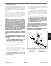
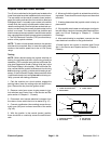
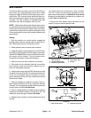
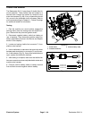
4. Verify coil resistance between terminals 85 and 86
with a multimeter (ohms setting) (Fig. 52). Resistance
should be approximately 72 ohms.
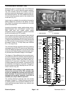
1. Exhaust muffler
2. Main power relay
3. Glow relay
4. Hood saddle
Figure 50
1
3
2
4
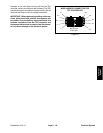
1. 48 VDC logic relay
2. Reel motor fuses
3. Generator air intake
Figure 51
2
3
1
Figure 52
86 87
85 30
85 86
87
30