


Reelmaster 5010- H Page 5 - 77 Electrical System
Service and Repairs
NOTE: See the Kubota Workshop Manual, Diesel En-
gine,05- E4BSeries forengine electricalcomponentre-
pair information.
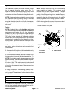
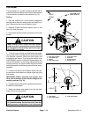
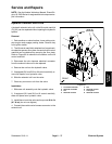
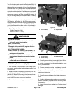
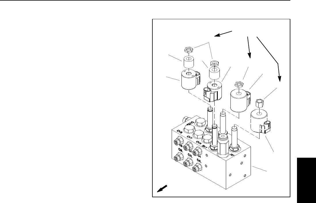
Hydraulic Solenoid Valve Coils
Ahydraulic solenoidvalve coilon thelift controlmanifold
(Fig. 83) can be replaced without opening the hydraulic
system.
Removal
1. Park machine on a level surface, lower cutting units,
stop engine and engage parking brake. Remove key
from ignition switch.
2. The lift control manifold is attached toa frame brack-
etunder theoperatorfloor plate.Access tothe liftcontrol
manifold can be obtained by r emoving the floor plate.
Refer to Figure 83 for solenoid coil locations on the lift
control manifold.
3. Disconnect the wire harness electrical connector
from the solenoid valve coil to be replaced.
4. Remove the nut from the hydraulic valve.
5. Ifequipped(SV1and SV3onliftcontrolmanifold),re-
move coil spacer from hydraulic valve.
6. Slide the solenoid coil from the valve.
7. Clean any corrosion or dirt from the valve.
Installation
1. Slide new coil assembly onto the hydraulic valve.
2. If equipped (SV1 and SV3 on lift control manifold),
slide coil spacer onto hydraulic valve.
3. Install the nut onto the valve and torque nut 60 in- lb
(6.7 N- m) (do not over tighten).
4. Connect the machine wire harness connector to the
solenoid coil.
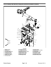
1. Lift control manifold
2. Solenoid coil SVRV
3. Nut
4. Solenoid coil SV2
5. Nut
6. Solenoid coil SV1
7. Coil spacer
8. Solenoid coil SV3
Figure 83
1
2
3
4
5
5
6
7
7
8
FRONT
60 in- lb
(6.7 N-m)
Electrical
System