


Reelmaster 5010- H
Cutting Units
Page 7 - 26
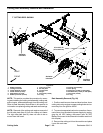
Cutting Reel Assembly Service
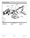
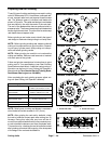
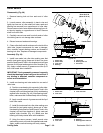
1. Cutting reel
2. Threaded insert (RH thread)
3. Bearing
4. Flocked seal
5. Special washer
6. Retaining ring
7. Reel shaft plug
8. Threaded insert (LH thread)
Figure 31
85 to 95 ft-lb
(115 to 128 N-m)
85 to 95 ft- lb
(115 to 128 N-m)
Loctite #242
Loctite #242
3
2
6
5
4
1
FRONT
RIGHT
(Right Hand Threads)
(Left Hand Threads)
7
8
3
4
7
6
5
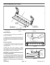
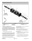
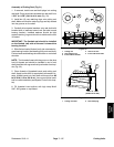
Disassembly of Cutting Reel (F ig. 31)
1. Remove threaded inserts (items 2 and 8) from cut-
ting reel.The threaded insert withthe grooveontheface
has LH threads and is in end of reel shaft identified with
a groove that is just inside of reel spider (Fig. 32). Use
correct spline insert tool for insert removal (see Special
Tools in this chapter).
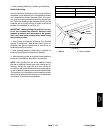
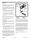
2. Slide bearings (item 3) from reel shaft.
3. Note orientation of flocked seals (item 4) for assem-
bly purposes (flocked (red) side orientated toward bear-
ing location). Remove flocked seals from reel shaft.
4. Note orientation of special washers (item 5) for as-
sembly purposes (flat side toward bearing location).
Carefully drive special washers from reel shaft.
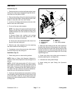
5. If necessary, remove reel shaft plugs (item 7) from
reel shaft.
6. Discard removed components and replace during
cutting reel assembly.
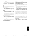
Inspection of Cutting Reel (Fig. 31)
1. Check the threaded inserts for excessive wear or
distortion. Replace inserts if damage is evident.
2. Inspect thereel shaft asfollows.If reeldamageis de-
tected, replace reel.
A. Check the reel shaft for bending and distortion by
placing the shaft ends in V- blocks.
B. Check the reel blades for bending or cracking.
C. Check the service limit of the reel diameter (see
Preparing a Reel for Grinding in this section).