


Reelmaster 5010- HPage 5 - 46Electrical System
Component Testing
For accurate resistance and/or continuity checks, elec-
trically disconnect the component being tested from the
circuit (e.g. unplug the ignition switch connector before
doing a continuity check of the switch).
NOTE: Electrical troubleshooting of any 12 volt power
connectioncanbe performedthroughvoltagedrop tests
without disconnecting the component.
NOTE: Use the InfoCenter display to test TEC con-
troller inputs and outputs before further troubleshooting
of an electrical problem on your Reelmaster. Inputs and
outputs can be tested using the InfoCenter Diagnostic
menu (see InfoCenter Display in this chapter).
NOTE: See the Kubota Workshop Manual, Diesel En-
gine,05- E4BSeriesfor engineelectricalcomponentre-
pair information.
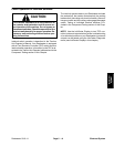
CAUTION
When testing electrical components for continu-
ity with a multimeter (ohms setting), make sure
that power to the circuit has been disconnected.
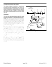
Ignition Switch
The ignition (key) switch has three (3) positions (OFF,
ON/PREHEAT and START). The switch is mounted on
the control console. The Toro Electronic Controller
(TEC) monitors the operation of the ignition switch.
Testing
NOTE: Before disconnecting the ignition switch for
testing, the switch and its circuit wiring should be tested
as a TEC input with the InfoCenter Display (see Diag-
nostics Screen(Engine Start item)in theInfoCenterDis-
play section of this chapter). If the InfoCenter Display
verifies that the ignition switch and circuit wiring are
functioning correctly, no further switch testing is neces-
sary. If the InfoCenter Display determines that the igni-
tion switch and circuit wiring are not functioning
correctly, proceed with ignition switch testing using the
following steps.
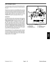
1. Park the machine on a level surface, engage the
parking brake, lower the cutting units and stop the en-
gine. Remove the key from the ignition switch.
2. Remove outside control arm cover to gain access to
ignition switch (see Control Arm in the Service and Re-
pairs section of Chapter 6 - Chassis).
3. Disconnect wire harness connector from the ignition
switch.
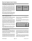
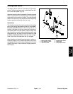
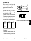
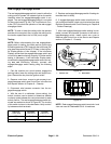
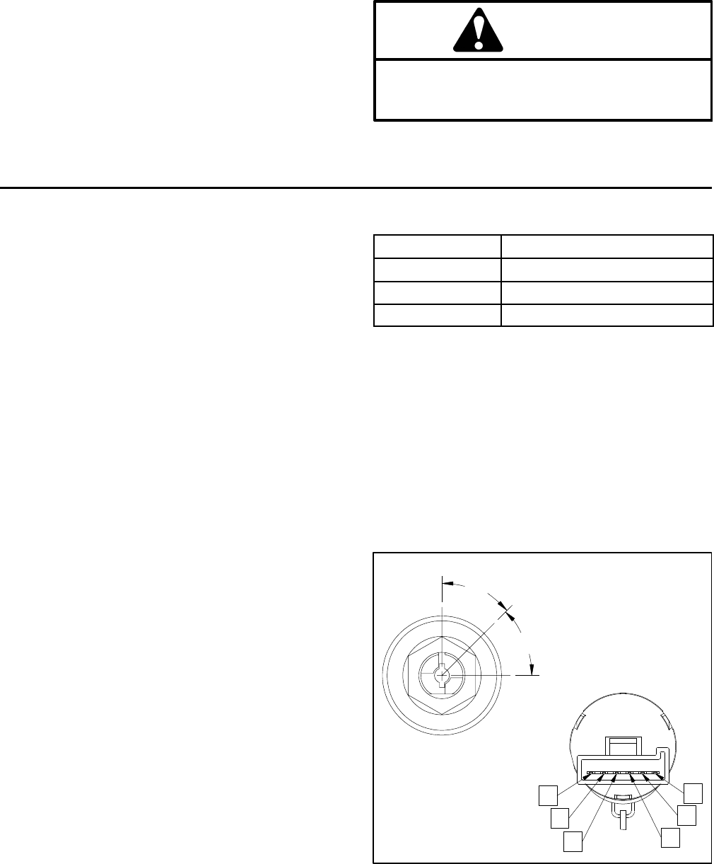
4. With the use of a multimeter (ohms setting), the
switch functions may be tested to determine whether
continuity exists between the various terminals for each
ignitionswitchposition. Theignition switchterminals are
marked as shown in Figure 31. The circuitry of this
switch is shown in the chart below. Verify continuity be-
tween switch terminals.
POSITION
CIRCUIT
OFF NONE
ON/PREHEAT B+I+A, X+Y
START B+I+S
5. Replace ignition switch if testing determines th at the
switch is faulty.
6. If ignition switch tests correctly and circuit problem
still exists, check wire harness (see Electrical Schemat-
ic and Circuit Drawings in Chapter 9 - Foldout Draw-
ings).
7. After ignitionswitchtesting iscomplete, connectwire
harness connector to the ignition s witch. Install control
arm cover to machine (see Control Arm in the Service
and Repairs section of Chapter 6 - Chassis).
Figure 31
S
B
I
A
Y
X
45
45
ON/PREHEAT
START
OFF