


Reelmaster 5010- H
Cutting Units
Page 7 - 38
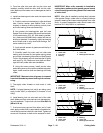
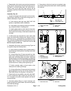
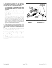
3. After assembly (including drive belt installation),
check alignment of pulleys with a straight edge placed
along the outer face of the drive pulley (Fig. 51).
A. The outer faces of the drive and driven pulleys
(not the idler pulley) should be in- line within 0.030”
(0.76 mm).
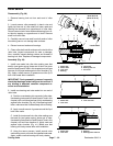
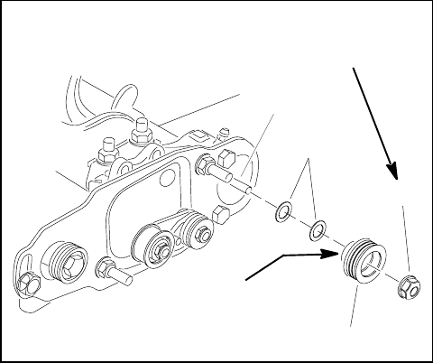
B. If necessary to align pulleys, r emove driven
pulley from brush shaft and add or remove flat wash-
er(s) until drive and driven pulleys are correctly
aligned (Fig. 52).
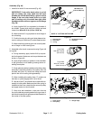
C. If driven pulley was removed from roller brush
shaft, apply antiseize lubricant to splines of pulley
bore and slide pulley onto shaft. Install and tighten
flange nut until pulley is seated onto shaft and then
torque flange nut from 27 to 33 ft-lb (37 to44 N- m).
Use a ½ wrench on roller brush shaft flats to prevent
shaft from rotating when tightening nut.
4. Check that brush is parallel to rear roller with 0.060”
(1.5mm)clearanceto lightcontactwithrearroller.Ifcon-
tactis incorrect,brusho peration willbeadversely affect-
ed.
5. Install cover (item 20).There should not be a set
screw installed in the bottom of the cover.
6. Lubricate grease fittings on brush housings until
grease purges past inboard seals. Wipe excess grease
from seals and fittings.
7. Once all rear roller brush service is completed, plug
the 48 VDC battery d isconnect back in before operating
the machine.
1. Flange nut
2. Driven pulley
3. Flat washer
4. Roller brush shaft
Figure 52
1
2
3
4
Antiseize
Lubricant
27 to 33 ft-lb
(37 to 44 N-m)