


Reelmaster 5010- HPage 5 - 48Electrical System
48 VDC System Fuses
Several fuses are used in the 48 VDC system (motor/
generator and cutting unit motors) for circuit protection.
Fuse Identification and Function
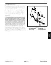
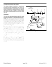
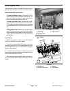
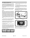
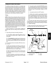
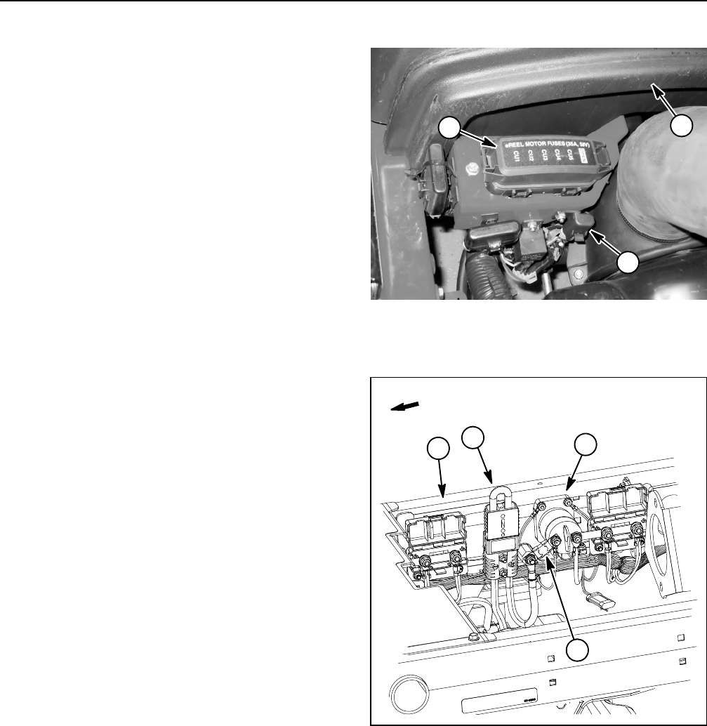
35 Amp Reel Motor Fuses: Protect the 48 VDC
power supply circuitsfor the electricreelmotors. The
reel motor fuses are located in a fuse holder behind
the hood saddle under the hood (Fig. 35).
10 Amp Logic Relay Fuse: Protects the 48 VDC
logiccircuitfor themotor/generatorand maincontac-
tor, The logic relay fuse is located in an in- line fuse
holder attached near the reel motor fuse holder (Fig.
35).
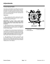
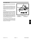
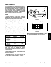
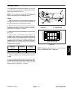
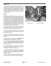
250 Amp Maxi Fuse: Protects main 48 VDC power
supply.The 250amp fuseis connectedtothe isolator
terminal and the main contactor behind the 48 VDC
battery disconnect attached to the right side frame
rail (Fig. 36).
Fuse Testing
1. Make sure that ignition switch is in the OFF position
and key is removed from ignition switch.
2. To prevent unexpected 48 VDC system component
operation, unplug the 48 VDC battery disconnect (see
48 VDC Battery Disconnect in the General Information
section of this chapter).
3. Locate an d remove fuse(s) for testing. Fuse should
have continuity between f use terminals. Replace fuse if
testing determines that it is faulty.
4. After fuse testing is completed, install removed cov-
ers and plug the 4 8 VDC battery disconnect into the
socket.
1. Hood saddle
2. Reel motor fuses
3. Logic relay fuse
Figure 35
2
1
3
1. RH frame rail
2. 48V battery disconnect
3. 250A fuse
4. Main contactor
Figure 36
2
1
FRONT
4
3