


Reelmaster 5010- H Page 5 - 71 Electrical System
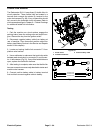
Temperature Sender
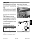
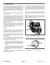
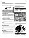
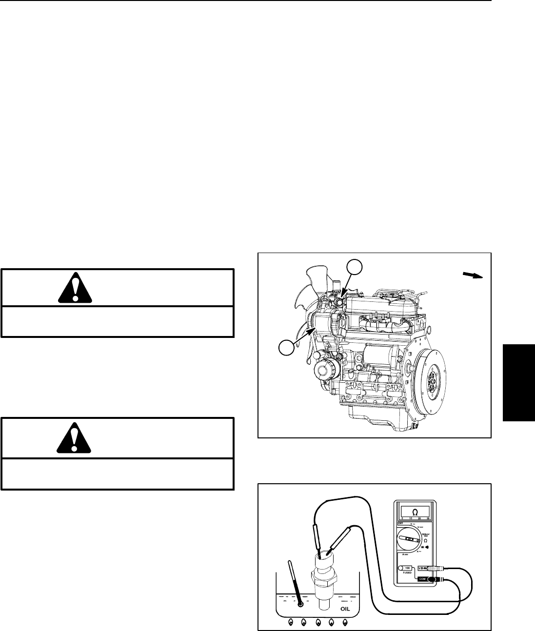
The temperature sender is located near the alternator
on thewater flangeattached to theengine cylinder head
(Fig. 72). The Toro Electronic Controller (TEC) monitors
the operation of the temperature sender.
The resistance of the temperature sender reduces as
the engine coolant temperature increases. The chang-
ing resistance of the temperature sender is used as an
analog input to the TEC controller to indicate engine
coolant temperature during machine operation.
Temperature Sender Test
1. Park the machine on a level surface, engage the
parking brake, lower the cutting units and stop the en-
gine. Remove the key from the ignition switch. Open
hoodtogainaccesstoengine.
2. Locate temperature sender on engine and discon-
nect wire harness connector from sender.
CAUTION
Make sure engine is cool before removing the
temperature sender from engine.
3. Lower coolant level in the engine and remove the
temperature sender from water flange.
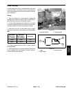
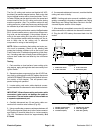
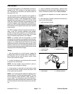
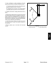
4. Put sender in a container of oil with a thermometer
and slowly heat the oil (Fig. 73).
CAUTION
Handle the hot oil with extreme care to prevent
personal injury or fire.
NOTE: Prior to taking resistance readings with a digital
multi meter, shortthe metertest leadstogether.The me-
ter will display a small resistance value (usually 0.5
ohms or less) due to the internal resistance of the meter
and test leads. Subtract this value from from the mea-
sured value of the component you are testing.
5. Check resistance of the sender with a multimeter
(ohms setting) as the oil temperature increases.
A. Themeter shouldindicate from11 .4 to13.6 ohms
at 68
o
F(20
o
C).
B. The metershould indicatefrom 2.3 to2.6 ohmsat
140
o
F(60
o
C).
C. Themeter shouldindicatefrom 0.6to 0.7ohms at
212
o
F(100
o
C).
6. Replace temperature sender if specifications are not
met.
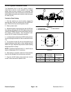
7. Install temperature sender to the water flange.
A. Clean threads of water flange and temperature
sender thoroughly. Apply thread sealant to the
threads of the sender.
B. Screwsenderinto thewater flange until itis finger
tight. Then, tighten sender an additional 2 to 3 full
turns.
C. Connect wire harness connector to sender.
8. Fill engine cooling system. Close and secure hood.
Figure 72
1. Temperature sender 2. Alternator
2
1
FRONT
Figure 73
Electrical
System