


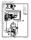
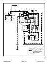
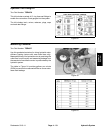

Reelmaster 5010- H Hydraulic SystemPage 4 - 19
Steering Circuit
A two section gear pump is coupled to the piston (trac-
tion) pump. Gear pump section P2 supplies hydraulic
flow to the steering control valve and for the traction
charge circuit. The hydraulic reservoir provides fluid for
the gear pumpthrough thesuction hose.Steeringcircuit
pressure is limited to 1000 PSI (70 bar) by a relief valve
(R10) located in the steering control.
With the steering wheel in the neutral position and the
engine running, flow enters the steering control valve at
the P port and goes through the steering control spool
valve, by- passing the rotary meter (V1) and steering
cylinder.Flow leavesthe controlvalve throughthe Tport
to the hydraulic oil filter and traction charge circuit.
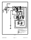
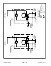
Left Turn (Fig. 15)
When a left turn is made with the engine r unning, the
turning of the steering wheel positions the steering con-
trol spool valve so that flow is directed through the bot-
tomof thespool.Flow enteringthesteering controlvalve
at the P port goes through the spool and is routed to two
places. First, most of the flow through the valve is by-
passed out the T port back to the hydraulic oil filter and
traction charge circuit. Second, the remainder of the
flow is drawn through the rotary meter (V1) and out the
L port. Pressure contracts the steering cylinder piston
for a left turn. The rotary meter ensures that the oil flow
to the steering cylinder is proportional to the amount of
turning on the steering wheel. Fluid leaving the steering
cylinder flows back through the steering control spool
valve and then out of the steering control valve through
theTportandtotheoilfilterandtractionchargecircuit.
The steering control valve returns to the neutral position
when turning is completed.
Right Turn (Fig. 15)
When a right turn is made with the engine running, the
turning of the steering wheel positions the steering con-
trol spool valve so that flow is directed through the top
of the spool. Flow entering the steering control valve at
the P port goes through the spool and is routed to two
places. As in a left turn, most of the flow through the
valve is by- passed out the T port back to the hydraulic
oil f ilter and traction charge circuit. Also like a left turn,
the remainder of the flow is drawn through rotary meter
(V1) but goes out port R. Pressure extends the steering
cylinder piston for a right turn. The rotary meter ensures
that the oil flow to the steering cylinder is proportional to
the amount of the turning on the steering wheel. Fluid
leaving the steering cylinder flows back through the
steering control spool valve then through the T port and
to the oil filter and traction charge circuit.
The steering control valve returns to the neutralposition
when turning is completed.
Hydraulic
System