


Reelmaster 5010- H Hydraulic SystemPage 4 - 49
The steering relief valve (R10) pressure test should be
performed to make sure that the steering circuit relief
pressure is correct.
Procedure for Steering Relief Valve (R10) Pressure
Test:
1. Parkmachineonalevelsurfacewiththecuttingunits
loweredand disengaged.Make sureengine isoff.Apply
the parking brake.
2. Read Precautions For Hydraulic Testing in this sec-
tion.
CAUTION
Before opening hydraulic system, operate all hy-
draulic controls to relieve system pressure and
avoid injury from pressurized hydraulic oil. See
Relieving HydraulicSystem Pressurein the Gen-
eral Information section of this chapter.
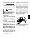
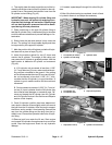
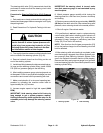
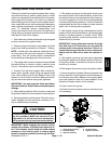
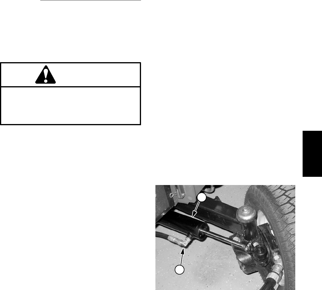
3. Thoroughlycleanthe areaaroundthe hydraulichose
at the rod end of the steering cylinder (Fig. 48).
4. Remove hydraulic hose from the fitting on the rod
end of the steering cylinder.
5. Install atee fittingbetweenthe disconnectedhydrau-
lic hose and the steering cylinder fitting. Install a 5000
PSI (350 bar) pressure gauge to the tee fitting.
6. After installing pressure gauge, start engine and run
at idle speed. Check for any hydraulic leakage from test
connections and correct before proceeding with test.
7. Make sure hydraulic oil is at normal operating tem-
perature by operating the machine under load for
approximately ten (10) minutes.
8. Increase engine speed to high idle speed (3000
RPM).
IMPORTANT: Hold steering wheel at full lock only
long enough to get a system pressure reading.
Holding the steering wheel against the stop for an
extended period may damage the steering control
valve.
IMPORTANT: As steering wheel is turned, make
sure that pressure gauge is not contacted by any
machine parts.
9. Watch pressure gauge carefully while turning the
steering wheel for a left hand turn ( counter- clockwise)
and holding.
10.System pressure should be approximately 1000 PSI
(69 bar) as the relief valve lifts. After determining relief
pressure, return steering wheel to the neutral position.
11.Shut off engine. Record test results.
12.If specification is not met, repair or replace steering
control valve (relief valve in steering control valve is not
replaceable). Gear pump section (P2) could also be
suspected of wear, damage or inefficiency (see Gear
Pump (P2) Flow Test in this section).
NOTE: If the flow from the 2nd gear pump section (P2)
is low, the traction charge circuit and steering circuit will
both be affected.
13.After steering relief valve testing is c ompleted, make
sure that engine is stopped, then relieve hydraulic sys-
tem pressure (See Relieving Hydraulic System Pres-
sure in the General Information section of this chapter).
Remove tee fitting and pressure gauge from hydraulic
hoseand steeringcylinder.Reconnecthydraulic hoseto
steering cylinder fitting.
1. Steering cylinder 2. Rod end fitting
Figure 48
1
2
Hydraulic
System