


Reelmaster 5010- HPage 5 - 40Electrical System
Electrical System Quick Checks
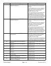
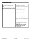
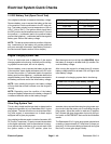
12 VDC Battery Test (Open Circuit Test)
Use a digital multimeter to measure the battery voltage.
Remove battery cover to access the battery at the rear
of the machine. Set the multimeter to the DC volts set-
ting. The battery should be at a temperature of 60
o
to
100
o
F(16
o
to 38
o
C). The ignition switch should be in
theOFF positionand allaccessoriesturnedoff.Connect
the positive (+) multimeter lead to the positive battery
post andthe negative(- )multimeter leadto thenegative
battery post. Record the battery voltage.
NOTE: Thistest providesa relativecondition ofthe bat-
tery. Load testing of the battery will provide additional
andmoreaccurateinformation(seeBatteryServicein
the Service and Repairs section of this chapter).
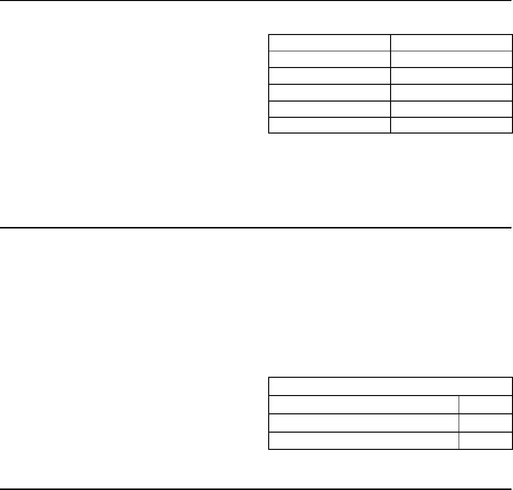
Voltage Measured
Battery Charge Level
12.68 volts or above Fully charged (100%)
12.45 volts 75% charged
12.24 volts 50% charged
12.06 volts 25% charged
11.89 volts or below 0% charged
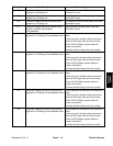
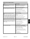
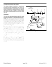
Engine Charging System Test
This is a simple test used to determine if the engine
chargingsystem isfunctioning. Itwilltell youifthe charg-
ing system has an output, but not its capacity.
Remove battery cover to access the battery at the rear
of the machine. Use a digital multimeter set to DC volts.
Connect the positive (+) multimeter lead to the positive
battery post and the negative (- ) multimeter lead to the
negative battery post. Keep the te st leads connected to
the battery posts and record the initial battery voltage.
NOTE: Upon starting the engine, the battery voltage
will drop and then should increase once the engine is
running.
NOTE: Depending upon the condition of the battery
charge and battery temperature, the battery voltage will
increase at different rates as the battery charges.
Start the engine and run at high idle (3000 RPM). Allow
the battery to charge for at least three (3) minutes. Re-
cord the battery voltage.
After running the engine for at least three (3) minutes,
battery voltage should be at least 0.50 volt higher than
initial battery voltage.
An example of a charging system that is functioning:
At least 0.50 volt over initial battery voltage.
Initial Battery Voltage =12.30V
Battery Voltage after 3 Minute Charge =12.95V
Difference = +0.65 V
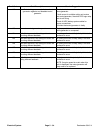
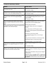
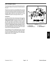
Glow Plug System Test
This is a fast, simple test that can help to determine the
integrityand operationof your Reelmaster 5010- Hglow
plug system. The test should be run anytime hard start-
ing (cold engine) is encountered on a d iesel engine
equippedwithaglowplugsystem.
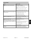
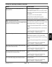
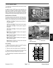
Use a digital multimeter and/or inductive Ammeter (AC/
DCCurrent Transducer).Properly connectthe ammeter
to the digital multimeter (refer to manufacturer’s instruc-
tions) and set the multimeter to the correct scale. With
the ignition switch in the OFF position, place the
ammeter pickup around the main glow plug power sup-
ply wire and read the meter prior to activating the glow
plug system. Adjust the meter to read zero (if applica-
ble). Activate the glow plug system by turning the igni-
tion switch to ON/PREHEAT and record the multimeter
results.
The Reelmaster 5010- H glow plug system should have
a reading of approximately 27 Amps total (9 Amps per
glow plug). If low current reading is observed during the
test, one (or more) glow plugs is faulty.