


Reelmaster 5010- HPage 5 - 76Electrical System
Fuel Pump
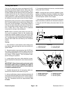
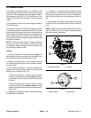
The Reelmaster electric fuel pump is attached to the i n-
side of theleft side framerail near the fuel tank(Fig. 81).
IMPORTANT: When testing fuel pump, make sure
that pump is not operated without fuel.
DANGER
Because diesel fuel is flammable, use caution
when handling it. Do not smoke while testing the
fuel pump. Do not test fuel pump while engine is
hot. Make sure that there is adequate ventilation
when testing.Always wipeup anyspilled fuelbe-
fore starting the engine.
Fuel Pump Capacity Test
1. Park the machine on a level surface, engage the
parking brake, lower the cutting units and stop the en-
gine.Remove thekey fromthe ignitionswitch. Raiseop-
erator seat and hood.
2. Disconnect wire harness electrical connector from
theengine fuelactuator toprevent theengine fromstart-
ing (see Fuel Actuator in this section).
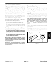
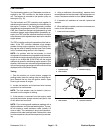
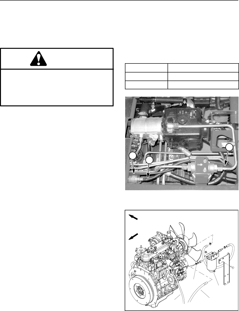
3. Disconnect fuel hose (pump discharge) from the
fuel/water separator inlet fitting (Fig. 82).
4. Make sure fuel hoses attached to the fuel pump, fuel
filter and fuel tank suction tube screen are free of ob-
structions.
5. Place disconnected hose intoa large, graduated cyl-
inder large enough to collect 1 quart (0.95 liter).
IMPORTANT: When testing the fuel pump, DO NOT
turn ignition switch to START.
6. Collect fuel in the graduated cylinder b y turning igni-
tion switch to theON/PREHEATposition. Allow pump to
run for fifteen (15) seconds, then return ignition switch
to OFF.
7. The amount of fuel collected in the graduated cylin-
der should be approximately 16 fl oz (475 ml) after fif-
teen (15) seconds.
8. Replace fuel pump if testing proves it to be faulty.
9. When testingis complete, installfuel hose tothe fuel/
water separator. Make sure to secure fuel hose with
hose clamp.
10.Connect wire harness electrical connector to the en-
gine fuel actuator.
11.Bleed the fuel system.
12.Lower and secure operator seat and hood.
Fuel Pump Specifications
Pump Capacity
64 fl oz/min (1.9 liters/min)
Pressure 7PSI(48.3kPa)
Current Draw 2.0 amp
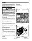
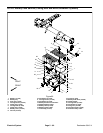
Figure 81
1. Fuel pump 2. Pump discharge hose
1
2
2
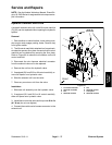
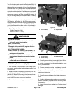
Figure 82
1. Fuel hose (from pump)
2. Hose clamp
3. Fuel/water separator
4. Fuel return hose
FRONT
RIGHT
2
3
1
4