


Reelmaster 5010- H Page 5 - 15 Electrical System
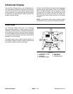
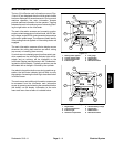
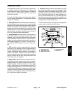
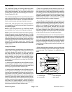
Diagnostics Screen
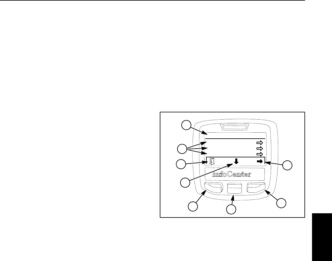
The diagnostics screen ( Fig. 21) lists the various states
of machine electrical components. The diagnostics
screen should be used to check operation of machine
controls and to verifythat switches and circuit wiring are
functioning correctly.
For each of the diagnostics screen items,inputs, qualifi-
ers and outputs are identified. The diagnostics screen
includes the following:
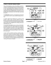
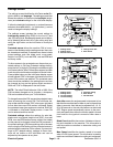
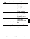
D Cutting Units identifies machine requirementsto al-
low the cutting units to raise and lower. Inputs indicate
the state of the joystick raise andlower switches andthe
positiono f theignition switch.Qualifiersinclude whether
the engine is running and the seat is occupied, that the
traction system is in the LOW range speed and inputs
are OK to lower and raise. Identified outputs consist of
SV1, SV2, SV3 and SVRV solenoid coils.
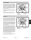
D Hi/Low Range identifies machine requirements to
allow LOW (mow) or HI (transport) speed range to be
engaged. Inputs indicate the state of the mow/transport
switch. Qualifiers identify the position of the seat switch,
whether the cutting units are raised and the position of
the engage/disengage (PTO) switch. There are no out-
puts from the TEC controller for the Hi/Low range func-
tion.
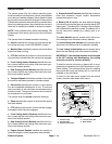
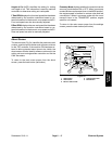
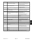
D PTO identifies machine requirements to allow the
cutting units to be engaged. Inputs indicate the state of
the PTO (engage/disengage) switch. Qualifiers identify
whether LOW speed range is selected, if the engine is
running, if the seat is occupied, if the e ngine tempera-
ture is not excessive and if the cutting units are lowered.
Outputs indicate that the rear cutting units and/or the
front cutting units are engaged.
D Engine Start identifies whether necessary TEC out-
puts exists to allowthe engine tostart and run. Inputs in-
dicate the state of the ignition switch (ON and START).
Qualifiers identify whether the joystick is in the neutral
position (neither lower nor raise engaged), that the PTO
(engage/disengage) switch is OFF, if the traction pedal
is in neutral and if the seat is occupied or parking brake
isapplied. Outputsindicate thatthe fuelactuator isener-
gizedand, whenthe ignition switchis inthe STARTposi-
tion, that the start output is energized.
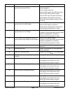
D Backlap identifies machine requirements to allow
the cutting unit backlap process to be engaged. Inputs
indicate the state of the backlap settings (ON or OFF
from Service menu screen) and the PTO status (ON or
OFF). Qualifiers identify that the parking brake is ap-
plied, the mow/transport lever is in the MOW position,
the cutting units are lowered and that the engine is run-
ning. Outputs indicate whether the front and/or the rear
cutting units are in the backlap mode.
To return to the main menu screen from the diagnostics
screen, press the back button (left button).
1. Diagnostics menu
2. Diagnostics items
3. Move to menu items
4. Choose menu item
5. Back but ton
Figure 21
Diagnostics
Cutting Units
Hi/Low Range
PTO
5
3
4
5
2
3
4
1
Electrical
System