


Reelmaster 5010- H Page 5 - 61 Electrical System
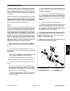
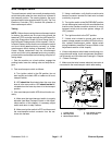
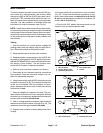
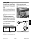
Main Contactor
The main contactor provides current to the 48 VDC sys-
tem circuits (e.g. motor/generator, reel motors). When
the ignition switch is ON, the 48 VDC logic relay is ener-
gized by the TEC controller which allows the main con-
tactor to be energized if allowed by the motor/generator
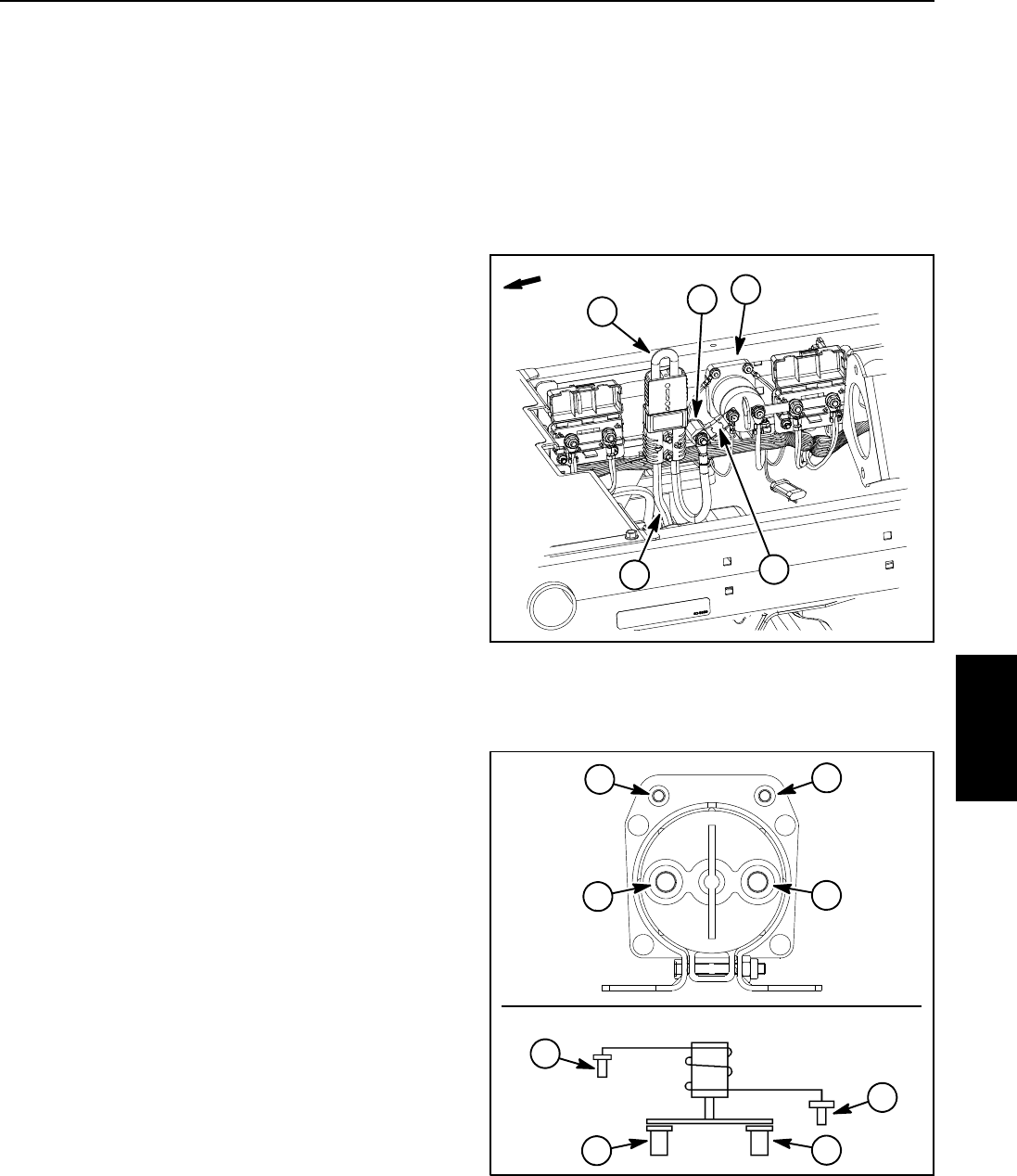
controller. The main contactor is attached to the right
side frame rail under the operator seat (Fig. 55).
NOTE: Ifelectricalproblemsexistwith themaincontac-
tor,a fault mayhave occurredthat wouldbe indicated by
a fault code on the InfoCenter Display. Before consider-
ingthat maincontactorservice workis necessary, check
for any existing fault codes that indicate problems with
the contactor.
Testing
1. Park the machine on a level surface, engage the
parking brake, lower the cutting units and stop the en-
gine. Remove the key from the ignition switch.
2. Raise operator seat to access main contactor.
3. Separate system components from the 48 VDC bat-
tery pack by unplugging the 48 VDC battery disconnect.
(see48 VDCBatteryDisconnectin theGeneralInforma-
tion section of this chapter). This will prevent unex-
pected 48 VDC system component operation.
4. Remove cover from main contactor (not shown).
5. Disconnect all wire harness electrical connections
from contactor. Note wire connector locations on con-
tactor for reassembly purposes.
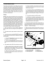
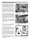
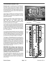
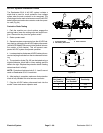
6. Usingjumper wires,apply48VDCdirectly acrossthe
contactor coil posts(Fig. 56). The contactor should click
as the coil is energized. With the contactor coil ener-
gized, resistance across the main contact posts should
be less than 1 ohm.
7. Remove voltage from contactor coil posts. The con-
tactor should click as the coil is de- energized. With the
contactor coil not energized, resistance across the main
contact posts should be infinite ohms.
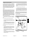
8. With no voltage applied to contactor posts, measure
resistance across the contactor coil posts (Fig. 56). The
resistance should be approximately 126 ohms.
9. Replace main contactor if testing determines that it
is faulty.
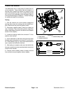
10.Connect electrical connections to main contactor
(Fig. 56). Torque nuts that secure connections to con-
tactor main contact posts from 40 to 50 in-l b (4.6 to 5.6
N-m)and nuts that secure connections to contactor coil
posts to 20 in-lb (2.2 N- m).
11.Plug the 48 VDC battery disconnect back into the
socket. Lower and secure operator seat.
Figure 55
2
3
5
4
1. Main contactor
2. Positive battery cable
3. 48V battery disconnect
4. Fuse (250A / 58V)
5. Isolator
1
FRONT
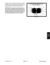
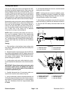
Figure 56
1. Main contact posts 2. Contactor coil posts
1
1
2
2
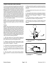
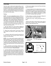
WIRING
DIAGRAM
2
2
1
1
CONTACTOR
Electrical
System