


Reelmaster 5010- HPage 5 - 62Electrical System
Toro Electronic Controller (TEC)
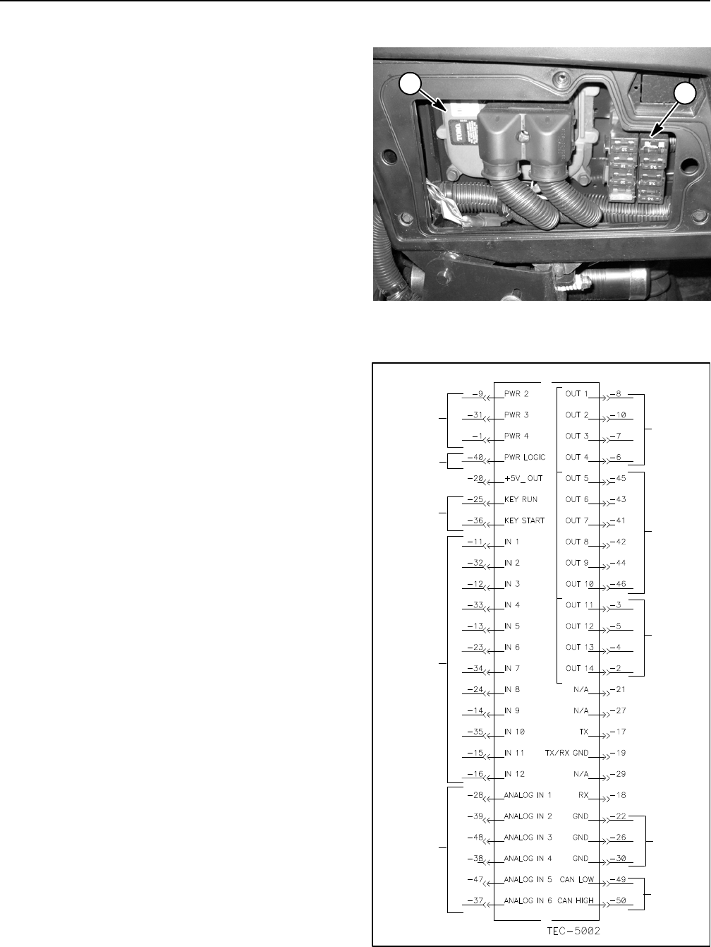
Reelmaster 5010- H machines use a Toro Electronic
Controller (TEC) to control electrical system operation.
The TEC controller senses the condition of various
switches (inputs) and directs power output to allow cer-
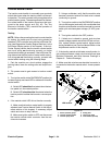
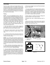
tain machine functions. The TEC is attached to the con-
trol arm behind the access panel on the outside of the
control arm (Fig. 57).
Logic power is provided to the controller as long as the
battery cables are connected to the battery. A 2 Amp
fuse (fuse F4) provides circuit protection for this logic
power to the controller.
Inputs from the ignition, neutral, parking brake, reel en-
gage/disengage, seat, mow/transport, joystick lower/
raise, reels down limit, engine speed, engine
temperature sender and engine oil pressure switches
are all monitored by the TEC controller.
Current output to the lift circuit hydraulic valve solenoid
coils, engine components (glow plug relay, start r elay,
fuel pump andfuel actuator)and reelcircuit 48 VDC log-
ic relay are controlled based on the inputs received by
the TEC controller. Circuit protection for TEC outputs is
provided by three (3) 7.5 Amp fuses (fuse locations
F2- 1, F2- 2 and F2- 3).
The InfoCenter Display should be used when checking
inputsand outputs ofthe TECused on your Reelmaster.
If the TEC detects a malfunction in any of the controlled
circuits,the InfoCenterDisplayc an alsobe usedto iden-
tify the fault (see InfoCenter Display in this chapter).
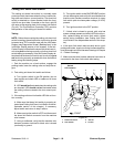
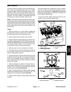
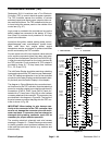
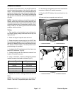
The diagram in Figure 58 depicts the connection termi-
nal functions for the TEC controller. Note that electrical
powerforcontrolleroutputsisprovidedthrough three(3)
connections (PWR 2, PWR 3 and PWR 4) each pro-
tected with a 7.5 amp fuse. A fifty (50) pin wire harness
connector attaches tothe controller.The connector pins
are identified in the diagram in Figure 58. The layout of
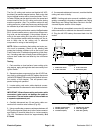
the wire harness connector that plugs into the TEC con-
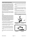
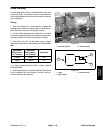
troller is shown in Fig. 59.
IMPORTANT: When testing for wire harness con-
tinuity at the connector for the TEC controller, take
care to not damage the connector pins with multi-
meter test leads. If connector pins are enlarged or
damaged during testing, connector repair will be
necessary for proper machine operation.
The machine electrical schematic and wire harness
drawingsin Chapter 10 - Foldout Drawings canbe used
to identify possible circuit problems between the con-
troller and the input/output devices (e.g. switches and
solenoid coils).
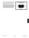
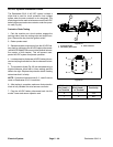
1. TEC controller 2. Fuse block
Figure 57
1
2
Figure 58
12V POWER
(7.5AFUSES)
12VLOGIC
IGNITION
SWITCH
INPUTS
DIGITAL
INPUTS
(OPEN/
ANALOG
INPUTS
POWER
(2AMPFUSE)
CLOSED)
(VARIABLE)
CANBUS
OUTPUTS
(PWR2)
GROUND
OUTPUTS
(PWR3)
OUTPUTS
(PWR4)