


Reelmaster 5010- HPage 5 - 70Electrical System
Hydraulic Solenoid Valve Coil
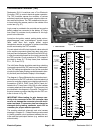
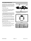
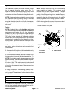
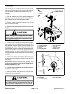
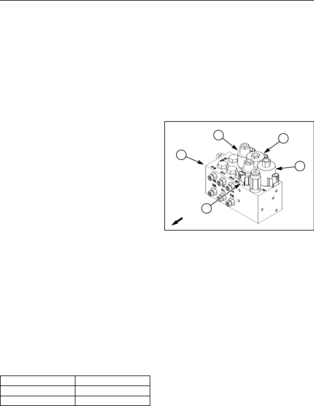
The Reelmaster hydraulic lift control manifold includes
four (4) solenoid valves for system control (Fig. 71).
When the solenoid coils are energized, hydraulic valve
shift occurs to control hydraulic flow. Testing of the coils
canbedonewiththecoilinstalledo n thehydraulic valve.
NOTE: If electrical problems exist with a solenoid valve
coil, a fault may have occurred that would be indicated
bya faultcodeon theInfoCenterDisplay.Before consid-
ering that solenoid valve coil service work is necessary,
check for anyexisting faultcodes thatindicate problems
withacoil.
Testing
NOTE: A solenoid valve coils should be tested as a
TECcontrollero utput withtheInfoCenterDisplay before
disconnecting and testing the coil (see Diagnostics
Screen (PTO item) in the InfoCenter Display section of
this chapter). The InfoCenter Display will identify if the
TEC output to the solenoid coil exists when machine
controls are in the correct position. If the TEC controller
output exists for a solenoid coil but the coil is not func-
tioning correctly, suspect a failed coil o r an open in the
solenoid valve coil circuit.
1. Park machine on level surface, lower cutting units,
stop engine, apply parking brake and remove key from
ignition switch.
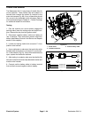
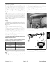
2. Access to the lift control manifold can be obtained by
removing the operator floor plate.
3. Disconnect wire harness electrical connector from
hydraulic solenoidvalve coilthatis tobe tested(Fig.71).
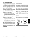
NOTE: Prior to taking small resistance readings with a
digital multimeter, short the meter test leads together.
The metermay displaya small resistance value(usually
0.5 ohms or less). This resistance is due to the internal
resistance of the meter and test leads. Subtract this val-
ue from from the measured value of the component you
are testing.
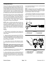
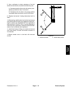
4. Using a multimeter (ohms setting), measure resis-
tance between the two connector terminals on the sole-
noid valve coil. The resistance for the solenoid coils is
identified below:
Solenoid Valve Coil
Resistance
SV1 and SV3 8.7 ohms
SV2 and SVRV 7.1 ohms
5. If solenoid coil resistance is incorrect, replace sole-
noid coil (see Hydraulic Solenoid Valve Coil in the Ser-
vice and Repairs section of this chapter).
NOTE: Solenoid valve coils SV2 and SVRV on the lift
control manifold are identical. The remaining two lift
manifold coils (SV1 and SV3) are identical. To assist in
troubleshooting, identical coils can be exchanged. If the
problem follows the exchanged coil, an electrical prob-
lem likely exists. If the problem remains unchanged,
something other than the solenoid coil is the problem
source (e.g. switch, circuit wiring, hydraulic problem).
6. After testing the coils, connect wire harness electri-
cal connector to the solenoid valve coil.
7. Install operator floor plate.
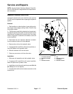
1. Lift manifold
2. SV3 solenoid
3. SV2 solenoid
4. SVRV solenoid
5. SV1 solenoid
Figure 71
4
1
3
5
2
FRONT