


Reelmaster 5010- H Page 5 - 49 Electrical System
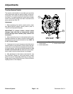
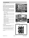
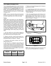
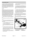
Engine Speed Switch
The engine speed switch is a momentary switch that is
used as an input for the TEC controller to raise or lower
the engine speed. When the switch is depressed and
held in the forward position, the engine speed will in-
crease. Conversely, when the rear of the switch is de-
pressed,engine speedwilldecrease. Theengine speed
switch is located on the control arm (Fig. 37).
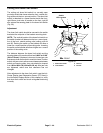
Testing
1. Park the machine on a level surface, engage the
parking brake, lower the cutting units and stop the en-
gine. Remove the key from the ignition switch.
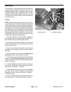
2. Disassemble control arm to gain access to engine
speedswitch(seeControlArmintheServiceandRe-
pairs section of Chapter 6 - Chassis).
3. Disconnect wire harness connector from the engine
speed switch.
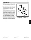
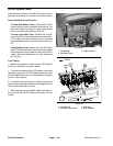
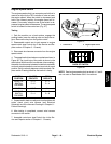
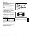
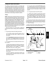
4. The speed switch terminals are marked as shown in
Figure 38. The circuit logic of the switch is shown in the
chart below.With theuse of amultimeter (ohms setting),
theswitchfunctionsmayb e testedto determinewhether
continuity exists between the various terminals for each
position. Verify continuitybetween switchterminals. Re-
place switch if testing identifies that switch is faulty.
SWITCH
POSITION
CLOSED
CIRCUITS
OPEN
CIRCUITS
FRONT OF
SWITCH
PRESSED
2+3
5+6
2+1
5+4
NEUTRAL NONE ALL
REAR OF
SWITCH
PRESSED
2+1
5+4
2+3
5+6
5. If speedswitch testscorrectly andcircuitproblemstill
exists, check circuit wire harness (see Electrical
Schematic a nd Wire Harness Drawings in Chapter 9 -
Foldout Drawings).
6. After testing is completed, connect wire harness
connector to the switch.
7. Assemble control arm (see Control Arm in the Ser-
vice and Repairs section of Chapter 6 - Chassis).
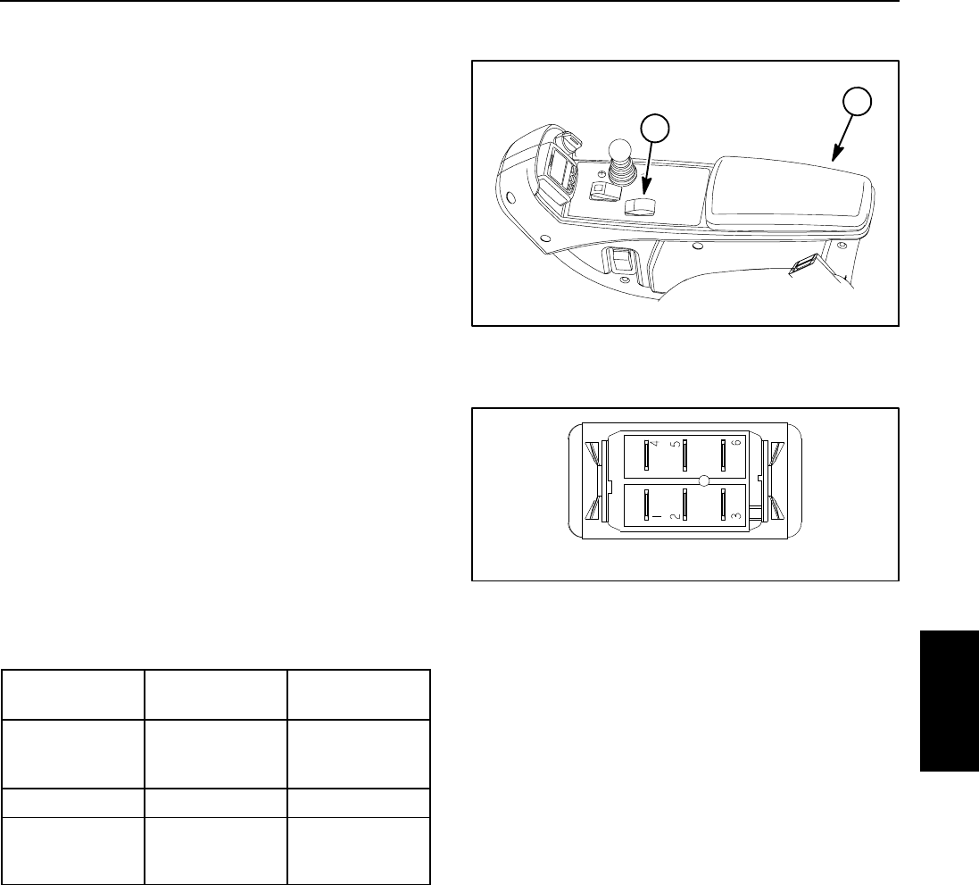
1. Console arm 2. Engine speed switch
Figure 37
2
1
Figure 38
BACK OF SWITCH
NOTE: Reel engine speed switch terminals 4, 5 and 6
are not used on Reelmaster 5010- H machines.
Electrical
System