


Reelmaster 5010- H Page 6 - 21 Chassis
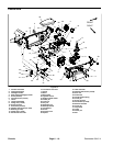
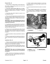
Removal (Fig. 15)
1. Park machine on a level surface, lower cutting units,
stop engine, engage parking brake and remove key
from the ignition switch.
2. Disconnect negative battery cable from 12 volt bat-
teryatrearofmachine(see12VoltBatteryServiceinthe
Service and Repairs section of Chapter 5 - Electrical
System).
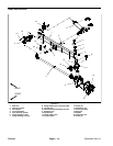
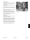
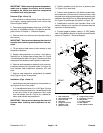
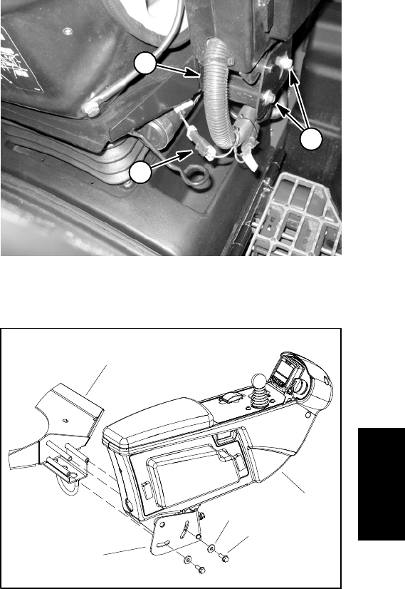
3. Disconnect seat switch electrical connector from
wire harness (Fig. 16).
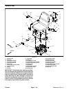
4. Remove two( 2) flangeheadscrewsand flatwashers
that secure retainer bracket assembly and control arm
assemblytoseat base(Fig.17).Remove retainerbrack-
et assembly.
IMPORTANT: Take care tonot damage the electrical
wire harness when removing seat and control arm
assembly from machine.
5. Carefully slide control armassembly from seat base.
Make sure that two (2) bushings remain in pivot of con-
trol arm assembly. Position and support control arm as-
sembly to allow seat removal.
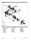
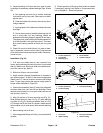
6. Remove four (4) socket head screws (item 15) and
flat washers (item 4) that secure seat and seat base to
seat adjusters. Note location of fasteners for assembly
purposes.
7. Support seat base to keep it positioned on seat ad-
justers.
8. Remove operator seat from seat base and seat ad-
justers. Note location of fasteners for assembly purpos-
es.
Installation (Fig. 15)
1. Position seat and seat base to seat adjusters. Use
forward set of mounting holes in bottom of seat when
aligning seat with seat base and adjusters.
2. Secure seatandseat baseto seatadjusters withfour
(4) flat washers (item 4) and socket head screws (item
15).
IMPORTANT: Take care to not damage electrical
wire harness when installing control arm assembly
to machine.
3. Make sure that two (2) bushings are positioned in
control arm pivot area. Carefully slide control arm as-
sembly onto seat base post.
4. Position retainer bracket assembly to control arm
and secure with two (2) flange head screws and flat
washers (Fig. 17).
5. Connect seat switch electrical connector to wire har-
ness.
6. Connect n egative battery cable to 12 volt battery at
rear of machine (see 12 Volt Battery Service in the Ser-
vice and Repairs section of Chapter 5 - Electrical Sys-
tem).
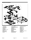
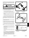
1. Seat switch lead
2. Wire harness
3. Flange screw
Figure 16
1
2
3
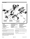
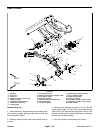
1. Seat base
2. Control arm assembly
3. Flange screw (2 used)
4. Flat washer (2 used)
5. Retainer bracket assy
Figure 17
1
2
3
4
5
Chassis