


Reelmaster 5010- H Page 5 - 55 Electrical System
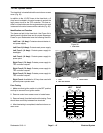
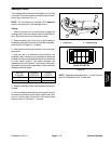
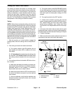
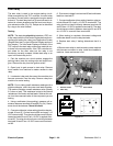
Cutting Unit Down Limit Switch
The cutting unit down limit switch is a normally open
proximity switch that closes when the front, outside cut-
ting unitsare in theturn- around position. The down limit
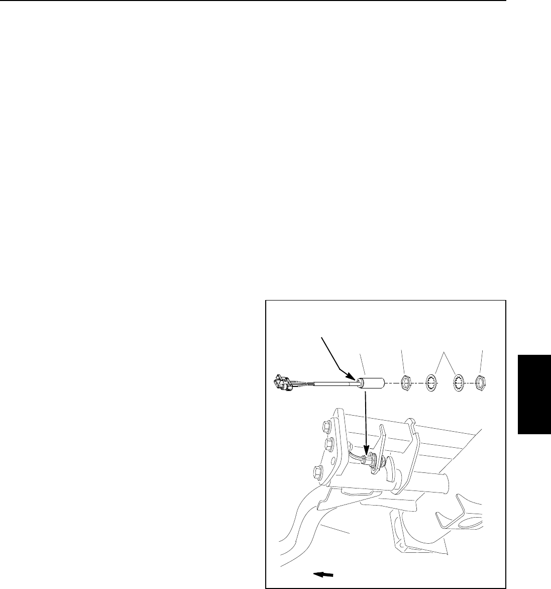
switch is attached to a frame bracket inside the front,
right lift arm pivot tube. A bracket on the front, right lift
arm acts as the sensing plate for the down limit switch
(Fig. 46). The Toro Electronic Controller (TEC) monitors
the operation of the cutting unit down limit switch.
Testing
NOTE: Before disconnecting the cutting unit down limit
switch for testing, the switch and its circuit wiring should
be tested as a TEC controller input with the InfoCenter
Display (see Diagnostics Screen (Backlap item) in the
InfoCenter Display section of this chapter). If the Info-
CenterDisplay verifiesthat thedown limitswitch andcir-
cuitwiring arefunctioning correctly, nofurther downlimit
switch testingis necessary. If theInfoCenter Display de-
termines that the down limit switch and circuit wiring are
not functioningcorrectly, proceed with downlimit switch
testing using the following steps.
1. Park the machine on a level surface, engage the
parking brake, lower the cutting units and stop the en-
gine.
2. Test cutting unit down limit switch as follows:
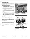
A. Turn ignition switch to the ON position (do not
start engine) and check LED on cable end of down
limit switch.
B. LEDshouldbe illuminatedwhenthe cuttingunits
are lowered. LED should not be illuminated when
the cutting units are raised to the turn around posi-
tion.
3. If the cutting unit down limit switch LED did not func-
tion correctly:
A. Make sure that down limit switch is properly ad-
justed (see CuttingUnit Down Limit Switch inthe Ad-
justments section of this chapter). If necessary,
adjust switch and return to step 2 above.
B. Make sure ignition switch is OFF and disconnect
the down limit switch connector from the machine
wire harness.
C. Using a multimeter, verify that the machine wire
harness connector terminal for black wire is closed
(continuity) to ground.
D. Turnignition switch tothe ON/PREHEAT position
(do not start engine)and verify with a multimeter that
machine wire harness connector terminal for down
limit switch pink wire has system voltage (12 VDC)
present.
E. Turn ignition switch to the OFF position.
F. If black wire is closed to ground, pink wire has
system voltage present and switch LEDdid not func-
tion, replace cutting unit down limit switch. Adjust
switch during installation (see Cutting Unit Down
Limit Switch in the Adjustments section of this chap-
ter).
4. If the down limit switch tests correctly and a circuit
problemstillexists,check circuitwireharness (seeElec-
trical Schematic andWire Harness Drawings inChapter
9 - Foldout Drawings).
5. Make sure that wire harness electrical connector is
connected to the down limit switch after testing.
1. Down limit switch
2. Lock washer
3. Jam nut
4. Lift arm
Figure 46
LED Location
FRONT
2
3
1
3
4
Switch
Electrical
System