


Reelmaster 5010- H
Cutting Units
Page 7 - 34
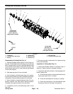
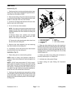
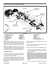
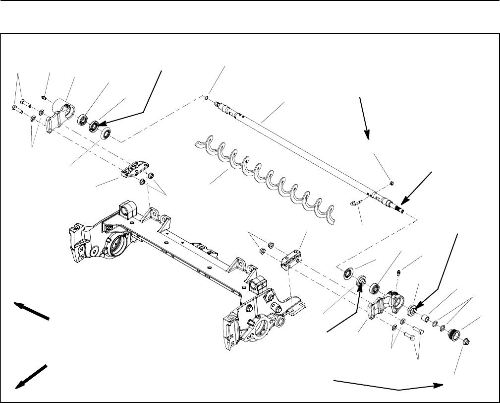
Rear Roller Brush (Optional)
1. Brush bearing housing (non-drive)
2. Brush bearing housing (drive)
3. O-ring
4. Roller brush shaft
5. Flange nut (4 used)
6. Mounting bracket (2 used)
7. Excluder seal (2 used)
8. Flat washer (4 used)
9. Cap screw (4 used)
10. Spacer
11. Flat washer (for pulley alignment)
12. Driven p ulley
13. Flange nut
14. Roller brush
15. Lock nut
16. J-bolt (2 used)
17. Grease fitting
18. Grease seal
19. Ball bearing
20. Grease fitting
21. Grease seal
22. Ball bearing
Figure 44
v
Antiseize
Lubricant
FRONT
RIGHT
FRONT
RIGHT
20 to 25 in-lb
(2.3 to 2.8 N-m)
27 to 33 ft-lb
(37to44N-m)
Grease
Seal Lip
2
3
6
8
9
10
11
13
1
5
7
12
14
18
16
17
18
19
20
4
21
22
5
8
9
7
6
15
Grease
Seal Lip
Grease
Seal Lip
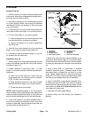
NOTE: Drive components for the rear roller brush are
located on the opposite side of the cutting unit from the
cutting reel motor. Figure 44 shows components used
when thebrush driveis onthe left side ofthe cutting unit.
NOTE: The Installation Instructions for the rear roller
brush kit has detailed information regarding assembly
and adjustment. Use those Instructions along with this
Service Manual when servicing the rear roller brush.
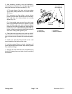
Disassembly (Fig. 44)
1. Position machine on a clean andlevel surface, lower
cutting units, stop engine,engage parking brake and re-
move key from the ignition switch.
2. To preventunexpected reel motor operation,discon-
nect motors from the electrical power supply by unplug-
ging the 48 VDC battery disconnect (see 48 VDC
BatteryDisconnectin theGeneralInformation sectionof
this chapter).
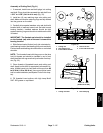
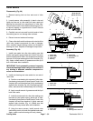
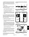
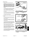
3. To remove roller brush from brush shaft:
A. Remove the non- drive brush bearing housing
(item 1) from cutting unit.
B. Slide excluder seal from roller brush shaft.
C. Remove locknut and J- bolt fromboth endsof the
brush.
D. While rotating brush, slide brush from the shaft.