


Reelmaster 5010- H Page 5 - 3 Electrical System
Toro Electronic Controller (TEC)
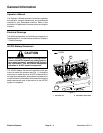
Reelmaster 5010- H machines use a Toro Electronic
Controller (TEC) to manage machine electrical func-
tions. The controller is microprocessor controlled t hat
senses the condition of various switches and sensors
(inputs). The controller then directs electrical power to
control appropriate machine functions (outputs) based
on the input state. Communication between the TEC
controller,theInfoCenterDisplay,thecuttingunit motors
and the motor/generator is provided bya CAN- bus sys-
tem. The status of inputsto the TEC controller as well as
outputs from the TEC controller can be monitored with
the InfoCenter Display.
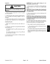
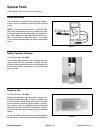
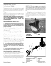
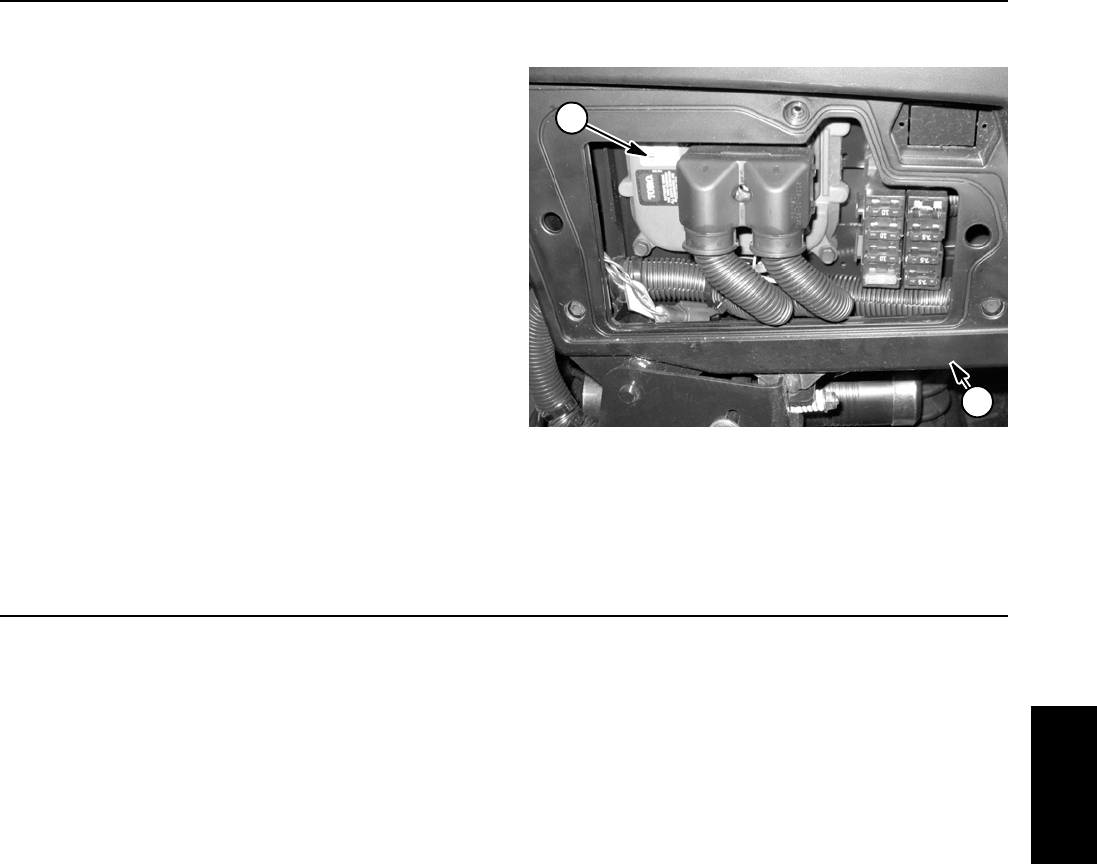
The TEC controller is located behind the access panel
on the outside of the control arm (Fig. 2).
IMPORTANT: To prevent machine electrical system
damage while welding on the machine, disconnect
thebatterycables fromthebatteries,disconnectthe
wire harness connectors from the Toro Electronic
Controller and disconnect the terminal connector
from the alternator.
1. Control arm 2. TEC controller
Figure 2
1
2
CAN- bus Communications
System communication between electrical components
on Reelmaster 5010- H machines is accomplished on
two (2) CAN- bus communication systems. These
CAN- bus systemsreduce thenumber of electricalcom-
ponents and connections used on the machine and al-
low the number of wires in the wire harness to be
reduced. The integration ofmachine electrical functions
also allows the InfoCenter Display to assist with electri-
cal system diagnostics.
One of these CAN- bus systems allows TEC controller
communication between machine 12 VDC components
(e.g. engine components, InfoCenter display). The sec-
ond CAN- bus system provides necessary control for
the electric cutting reels system (motor/generator, cut-
ting reel motors). An isolation module is included in the
machine electrical system to allow communication be-
tween the two systems while maintaining ground isola-
tion for the 48 VDC system.
CANidentifies theController Area Networks that isused
on the Reelmaster. Two (2) specially designed, twisted
wires form the bus for both of the networks used on the
Hybrid machines. These wires provide the data path-
ways between machine components. The engineering
term for these two (2) wires a re CAN- high and CAN-
low. At the ends of the twisted pair of bus wires are 120
ohm termination resistors. Thebus wiresfor the12 VDC
circuitsareblack/whiteandred/whiteandthebuswires
for the 48 VDC circuits are green and yellow.
Each of the components that is controlled by the CAN-
buslinkneedsonlyfour(4)wirestooperateandcommu-
nicate to the system: CAN High, CAN Low, B+ (power)
and ground. TheCAN- bus needsthe ignition switchON
input for the TEC, InfoCenter Display, motor/generator
and cutting unit motors to be activated.
IMPORTANT: The termination resistors at the ends
of the bus wires are required for proper electrical
system operation.
Electrical
System