


Reelmaster 5010- H Hydraulic SystemPage 4 - 35
5. Start engine and run at idle speed. Check for any hy-
draulic leakage from test connections and correct be-
fore proceeding with test.
6. Make sure hydraulic oil is at normal operating tem-
perature by operating the machine under load for
approximately ten (10) minutes.
7. Make sure that traction pedal is in neutral, the steer-
ing wheel is stationary and parking brake is engaged.
8. Increase engine speed to high idle speed (3000
RPM) and monitor pressure gauge to determine no load
charge pressure. Record test results.
GAUGE READING TO BE approximately 200 to
250 PSI (13.8 to 17.2 bar)
9. Next, determine charge pressureunder tractionload
by operatingthemachinein adirectforwardand reverse
direction (not steering). Make sure that engine is run-
ning at full speed (3000 RPM). Apply the brakes and
pressthe tractionpedal inthef orward directionand then
to reverse while monitoring the pressure gauge. Stop
engine and record test results.
GAUGE READING TO BE approximately 150 to
250 PSI (13.8 to 17.2 bar)
10.Compare measured charge pressure from step 8
with pressure from step 9:
A. If charge pressure isgood under no load (step 8),
but drops below specification when under traction
load (step 9), the piston (traction) pump should be
suspected of wear and inefficiency. When the pump
is worn ordamaged, the chargesystem is not able to
replenish lost traction circuit oil due to excessive
leakage in the worn pump.
B. If there is no charge pressure, or pressure is low,
check for restrictionin gear pump intake line.Inspect
charge relief valve and valve seat in the piston (trac-
tion) pump (see Piston (Traction) Pump Service in
the Service and Repairs section of this chapter).
Also, consider a worn or damaged gear pump sec-
tion (P2) (see Gear Pump Flow Test in this section).
NOTE: If gear pump (P2) is worn or damaged, both
charge circuit and steering circuit will be affected.
11.After charge pressure testing is completed, make
sure that engine is not running and then relieve hydrau-
lic system pressure (See Relieving Hydraulic System
Pressure in the General Information section of this
chapter).Remove pressure gauge from test port and in-
stall dust cap to test port.
12.Lower and secure operator seat.
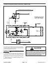
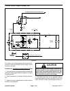
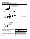
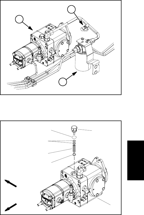
1. Piston (traction) pump
2. Oil filter
3. Test fitting
Figure 30
1
3
2
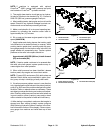
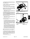
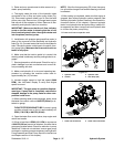
1. Piston (traction) pump
2. Plug
3. O-ring
4. Shim kit
5. Spring
6. Charge relief poppet
Figure 31
FRONT
RIGHT
2
3
4
1
5
6
Hydraulic
System