


Reelmaster 5010- H Hydraulic SystemPage 4 - 99
3. Label all hydraulic connections f or assembly pur-
poses. Thoroughly clean hydraulic hose ends prior to
disconnecting hoses from the steering cylinder.
4. Disconnect hydraulic hoses from fittings in steering
cylinder.
5. Put capsor plugs ondisconnected hosesand fittings
to prevent contamination.
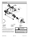
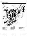
6. Remove two (2) jam nuts(item 11) that secure steer-
ing cylinder toaxle. Remove cotter pin(item 12),washer
(item 14)and slotted hex nut(item 13) that securesteer-
ing cylinder to RH drag link.
7. Separate ball joints from axle assembly and remove
steering cylinder from machine.
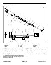
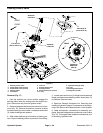
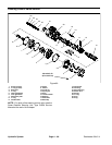
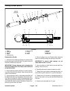
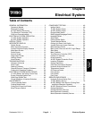
8. If necessary, remove ball joints from steering cylin-
derbarreland shaft(Fig. 82).Ifball jointisto beremoved
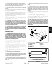
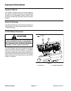
from cylinder shaft, fully retract cylinder shaft and mea-
sure center to center length to ease installation of ball
joint onto cylinder shaft (Fig. 83).
9. If hydraulic fittings are to be removed from steering
cylinder, mark fitting orientation to allow correct assem-
bly. Remove fittings from steering cylinder and discard
O-rings.
Installation (Fig. 81)
1. If hydraulicfittings wereremoved fromsteeringcylin-
der,lubricate new O- rings with clean hydraulic oil, posi-
tion O- rings to fittings and install fittings into steering
cylinder ports (see Hydraulic Fitting Installation in the
General Information section of this chapter). Make sure
that fittings are orientated correctly.
2. Ifremoved,pressball jointinto barrelandsecurewith
retaining ring. Make sure that retaining ring is fully seat-
ed in groove in steering cylinder barrel.
3. If ball joint was removed from cylinder shaft, fully re-
tract cylindershaft andthread balljointonto shaftso that
center to center length is as measured during removal
process. Tighten clamp bolt and nut.
4. Thoroughly clean tapers on ball joints and axle as-
sembly.
5. Position steering cylinder to machine.
6. Secure steering cylinder to axle with jam nuts (item
11). Tighten firstjam nut andthen, whileholding first jam
nut with wrench, tighten second jam nut.
7. Secure steering cylinder to RH drag link with washer
(item 14) and slotted hex nut (item 13). Install cotter pin
(item 12).
8. Remove caps and plugs from hydraulic hoses and
fittings.
9. Lubricate and install new O- rings on steering cylin-
der fittings. Correctly connect hydraulic hoses to steer-
ing cylinder fittings (see Hydraulic Hose and Tube
Installation in the General Information section of this
chapter).
10.Check oil level in hydraulic reservoir and add correct
oil if necessary.
11.Lubricate cylinder ball joint grease fittings.
12.Follow Hydraulic System Start- up procedures (see
Hydraulic System Start- up in this section).
13.Check that steering cylinder does not contact the
axle or frame as cylinder moves from fully retracted to
fully e xtended. Also, check that distance between the
drag links and steering stops are equal on both sides of
the machine. If necessary, adjust location of ball joint on
cylinder shaft.
1. Steering cylinder
2. Ball joint
3. Retaining ring
4. Grease fitting
5. Ball joint
6. Hex nut
7. Cap screw
8. Seal
9. Grease fitting
Figure 82
1
2
3
4
5
6
7
8
9
Figure 83
MEASURE CENTER TO CENTER LENGTH
FOR ASSEMBLY PURPOSES
Hydraulic
System