


Reelmaster 5010- H Hydraulic SystemPage 4 - 47
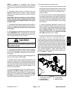
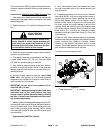
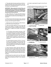
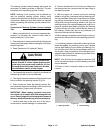
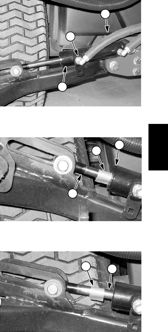
4. Thoroughly clean the area around the end of the hy-
draulic hose at ther od end of the lift cylinder for the sup-
ported lift arm. Disconnect the hydraulic hose from the
lift cylinder rod end fitting (Fig. 44).
IMPORTANT: When capping lift cylinder fitting and
hydraulic hose end, use a steel cap and plug to en-
sure that fluid leakage will not occur. Plastic plugs
will not hold hydraulic pressure that will be devel-
oped during this test p rocedure.
5. Place a steel cap on the open lift cylinder fitting to
seal the lift cylinder. Also, install a steel plug in the open
endof thedisconnected hoseto preventleakageor con-
tamination.
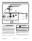
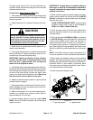
6. Slowly lower the jack and remove it from under the
lift arm. The cutting unit s hould settle slightly and then
be supported by the capped lift cylinder.
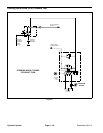
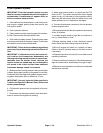
7. Mark theposition ofthelift cylinderrod atthe liftcylin-
der head with a piece of tape (Fig. 45).
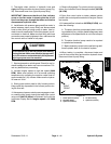
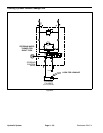
8. Leave the machine parked for two (2) hours and
monitor the lift cylinder. The weight of the cutting unit
may cause the lift cylinder to gradually extend. Use the
tape location to determine lift cylinder rod movement
(Fig. 46).
A. If lift cylinder rod movement is less than 1.250”
(31.7 mm)after two(2) hours,makesurethat thecut-
ting unit has not settled to the ground. If the cutting
unitis stillsuspendedafter two(2)hoursand liftcylin-
der rod movement is less t han 1.250” (31.7 mm),
consider that the lift cylinder is in good condition. A
cylinder in good, usable condition will show minimal
movement.
B. Rod movement in excess of 1.250” (31.7 mm) af-
ter two (2) hours indicates that the lift cylinder may
have internal seal damage or excessive wear. Re-
move and inspect the lift cylinder (see Lift Cylinder
and Lift Cylinder Service in the Service and Repairs
section of this chapter).
9. Once lift cylinder condition has been determined,
use a jack to raise the lift arm slightly which will remove
the load from the lift cylinder. Allow the jack to support
the lift arm and to prevent it from lowering. Remove the
capfromthecylinderfittingandtheplugfromthehy-
draulic hose. Connect the hydraulic hose to the lift cylin-
der fitting.
10.Remove jack from under the lift arm. Start engine
and operate lift cylinders through several up and down
cycles. Stop the engine and check for any hydraulic
leakage.
11.If needed, repeat steps3 through 9 forother lift cylin-
ders.
12.After lift cylinder testing is completed, check oil level
in hydraulic reservoir and adjust as necessary.
1. Lift cylinder (#5 shown)
2. Cylinder rod end fitting
3. Hydraulic hose
Figure 44
3
2
1
1. Lift cylinder rod
2. Lift cylinder head
3. Tape (initial position)
Figure 45
2
1
3
1. Tape (after 2 hours) 2. Cylinder rod movement
Figure 46
2
1
Hydraulic
System