


Reelmaster 5010- H Hydraulic SystemPage 4 - 17
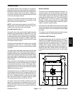
Lift Circuit: Lower Cutting Units
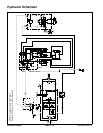
A two section gear pump is coupled to the piston (trac-
tion) pump. Gear pump section (P1) supplies hydraulic
flow to the lift control manifold and ultimately for the lift
cylinders. The hydraulic reservoir provides fluid for the
gearpumpthroughthe suctionhose.Lift circuitpressure
is limited to2000 PSI (138 bar)b y a solenoid relief valve
(SVRV) located in the lift control manifold.
The lift control manifold includes four (4) electrically op-
erated solenoid valves. Valve (SVRV) is used to direct
gear pump flow to the lift cylinders when energized or
bypass pump flow back to the reservoir when de- ener-
gized. Valve (SV2) is used to direct oil f low to retract the
lift cylinders when energized or extend them when de-
energized. Valve (SV1) allows hydraulic flow to the front
lift cylinders when energized. Valve (SV3) allows hy-
draulic flow to the rear lift cylinders when energized.
Lift circuit pressure can be monitored at lift control man-
ifold port G4.
The TEC controller uses inputs from various m achine
switchesto determinewhenlift manifoldsolenoidvalves
(SV1, SV2, SV3 and SVRV) are to be energized. The
TECalsoprovides apartialraisepositionof thefrontout-
side cutting units.
During conditions of not raising or lowering the cutting
units(joystick in the neutral (center) position), all four (4)
lift manifoldsolenoid valves(SV1, SV2,SV3 andSVRV)
are de- energized. Hy draulic flow from gear pump sec-
tion (P1) by- passes thelift cylinders tothe oil cooler and
then to the hydraulic reservoir.
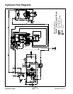
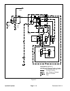
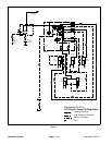
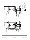
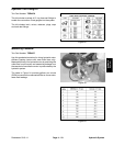
Lower Cutting Units (Fig. 14)
When the joystick is moved to the lower position, sole-
noid valve (SVRV) energizes along with solenoid valves
(SV1) and (SV3). Solenoid valve (SV2) is in its normally
de-energized position, and directs oil flow to the piston
end of the lift cylinders. Hydraulic pressure against the
piston side of the cylinder causes the shafts to extend,
and lower the cutting units. The piloted check valves in
the lift control manifold (CV1, CV4, CV5 and CV23) are
shifted by hydraulic pressure to allow return flow from
the extending lift cylinders. Fixed orifices in the lift con-
trol manifold (C1, C4, C5 and C23) co ntrol the lowering
speedbyprovidingarestriction for the return flow from
the lift cylinders.
Because cutting unit weight assists in extending the lift
cylinders when lowering the cutting units, less hydraulic
pressure is necessary during the cutting unit lowering
operation.Lift circuit lower relief valve (R7)allows liftcir-
cuit pressure to be limited to 500 PSI (35 bar) while low-
ering the cutting units.
NOTE: Adjustment of lift circuit lower relief valve (R7)
is not recommended.
When the joystick is returned to the neutral (center)
position, the solenoid valves are de- energized and the
lift cylinders (and cutting units) are held in the lowered
position.
Hydraulic
System