


Reelmaster 5010- H
Cutting Units
Page 7 - 31
Rear Roller
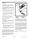
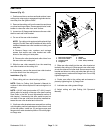
Removal (Fig. 37)
1. Position machine on a clean andlevel surface, lower
cutting units, stopengine, engage parking brake and re-
move key from the ignition switch.
2. Remove the cutting unit from the machine and place
onalevelworkingsurface.Place support blocks under
bedbar to raise rear roller from work surface.
3. Loosen two (2) flange nuts that secure the rear roller
shaft to each rear roller bracket.
4. On one of the rear roller brackets:
NOTE: On cutting units equipped with optional High
Height of Cut Kit, there will be additional roller shims
installed between rear roller bracket and cut ting unit
side plate.
A. Remove flange nuts, washers and carriage
screws that secure rear roller bracket and roller
shims to the cutting unit side plate.
B. Remove the roller bracket and roller shims from
the rear roller and cutting unit.
5. Slide the rear roller assembly from the remaining
rear roller bracket on the cutting unit.
6. If necessary, remove the second rear roller bracket
and roller shims from the cutting unit.
Installation (Fig. 37)
1. Place cutting unit on a level working surface.
NOTE: Refer to Cutting Unit Operator’s Manual for
number of roller shims required for various height of cut
settings.
NOTE: A 0.010” shim (part number 107- 4001) is avail-
able to allow for leveling of the rear roller (see Leveling
Rear Roller in the Set- up and Adjustments section of
this chapter). If necessary, this shim would be used on
one side of the rear roller and should be installed be-
tween the rear roller bracket and roller shim.
2. Ifboth rearroller bracketswere removedfromcutting
unit side plate, position brackets and roller shims to one
of the side plates. Install two (2) carriage screws and
flange nutsto retainbracketin position.Do notfullytight-
en flange nuts.
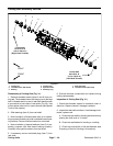
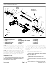
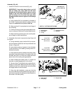
1. Rear roller assembly
2. Rear roller bracket
3. Carriage screw
4. Flange nut
5. Washer
6. Roller shim
7. 0.010” shim (if needed)
Figure 37
1
2
3
4
5
6
5
7
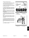
3. Slide rear roller shaft into the rear roller bracket at-
tached to thec utting unit. Slide second rear rollerb rack-
et onto the otherend ofroller shaft.Secure second roller
bracket and shims to cutting unit side plate with two (2)
carriage screws, washers and flange nuts. Do not fully
tighten flange nuts.
4. Center rear roller to th e cutting reel and secure in
place by tightening four (4) flange nuts.
5. Lubricate rear roller grease fittings.
6. Adjust cutting unit ( see Cutting Unit Operator’s
Manual).
Cutting
Units