


Reelmaster 5010- H Hydraulic SystemPage 4 - 71
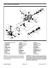
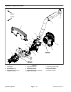
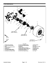
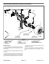
Removal (Fig. 62)
1. Park themachine on alevel surface,engage parking
brake, lower cutting units and stop engine. Remove key
from the ignition switch.
2. Raise and support hood and operator seat. Lift hood
saddle (item 1) from frame brackets and remove from
machine.
3. Loosen hose clamp that secures air intake hose
(item 2) to upper intake shroud. Carefully slide intake
hose from upper shroud.
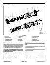
4. Remove intake shrouds (items 6 and 7) and brush
seals (item 8) from machine.
A. Remove four (4) flange head screws (item 4) and
flange n u ts (item 5) that secure upper and lower in-
take shrouds.
B. Separatetabs onupper shroudfrom slots on low-
er shroud. Remove shrouds and brush seals from
machine.
C. Note location of four (4) compression limiter
spacers in the upper shroud mounting holes.
5. Remove cap screws (item 13) and flange nuts (item
14)that securedriveshaft yokestohydraulic pumpinput
shaft and motor/generator output shaft.
6. Slide drive shaft yokes from hydraulic pump and mo-
tor/generator shafts and remove drive shaft a ssembly
from machine.
Installation (Fig. 62)
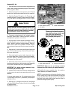
1. Apply antiseize lubricant to hydraulic pump input
shaft and motor/generator output shaft.
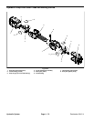
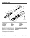
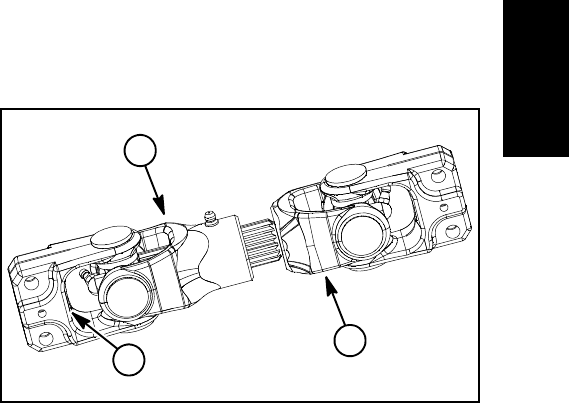
2. Position drive shaft assembly to hydraulic pump and
motor/generator shafts. The drive shaft male yoke
should beinstalled onto motor/generatorshaft (Fig. 63).
Position female yoke fully onto pump shaft so the shaft
end is flush with the inside of the yoke flange.
3. Secure driveshaftyokes top ump andmotor/genera-
tor shafts with two (2) cap screws (item 5) and flange
nuts (item 9).
4. Lubricate drive shaft grease fittings.
5. Secure intake shrouds ( items 6 and 7) and brush
seals (item 8) to machine.
A. Make surethat four (4) compression limiter spac-
ers are placed in the mounting holes in the upper in-
take shroud.
B. Position intake shrouds and brush seals around
drive shaft. Make sure that brush seals fit in grooves
of shrouds and grooves in shrouds fit onto flange on
motor/generator cover.Insert upper shroud tabs into
lower shroud openings.
C. Secure upper and lower intake shrouds with four
(4) flange headscrews (item 4)and flange nuts (item
5).
6. Carefully slide intake hose (item 2) onto upper
shroud and secure in place with hose clamp.
7. Install hood saddle (item 1) onto frame brackets.
Lower and secure hood and operator seat.
1. Male yoke (generator)
2. Female yoke (pump)
3. Inside of flange
Figure 63
2
1
3
Hydraulic
System