


Reelmaster 5010- H Page 5 - 83 Electrical System
The48 voltbatterypackused intheReelmaster 5010- H
electric reel drive system is composed of four (4) 12 volt
batteries that are connected in series. The batteries are
absorbed glass mat (AGM), valve regulated batteries
that aremaintenance free withno provisionfor checking
oradjustingelectrolyte level.Thebatteries areequipped
with a low pressure venting system designed to release
excess gas pressure and then automatically reseal. A
low self discharge rate prevents deterioration of battery
performance during non- use or storage.
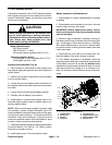
Before performing any service on the batteries in the 48
VDC system, disconnect the 48 VDC system compo-
nents from the electrical power supply by separating the
48VDC batterydisconnect (see48VDCBatteryDiscon-
nect in the General Information section of this chapter).
This will prevent unexpected system operation.
Battery Specifications
Battery capacity 53 AH
650 CCA at 0
o
F(-18
o
C)
WARNING
POTENTIAL HAZARD:
The battery terminals, metal tools and metal ve-
hicle parts could short together.
WHAT CAN HAPPEN:
Sparks can cause battery gasses to explode.
Damaged cables could short against metal ve-
hicle parts and cause sparks.
HOW TO AVOID THE HAZARD:
When removing or installing the batteries, do
notallowthe batteryterminalsto shortagainst
metal parts of the vehicle.
Donotallow metaltoolsor metalvehicleparts to
short between the battery terminals or battery
cables.
Always keep the battery retainers in place to
protect and secure the batteries.
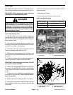
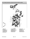
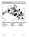
48 VDC Battery Pa ck Removal (Fig. 85)
1. Park machine on level surface, lower cutting units,
stop engine, apply parking brake and remove key from
ignition switch.
2. Separate system components from the 48 VDC bat-
tery pack by unplugging the 48 VDC battery disconnect.
(see48 VDCBatteryDisconnectin theGeneralInforma-
tion section of this chapter). This will prevent unex-
pected 48 VDC system component operation.
3. Remove battery covers to gain access to batteries.
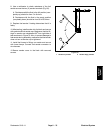
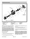
1. RH front battery
2. LH front battery
3. Positive terminal
4. Jumper cable
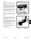
Figure 86
1
2
3
3
4
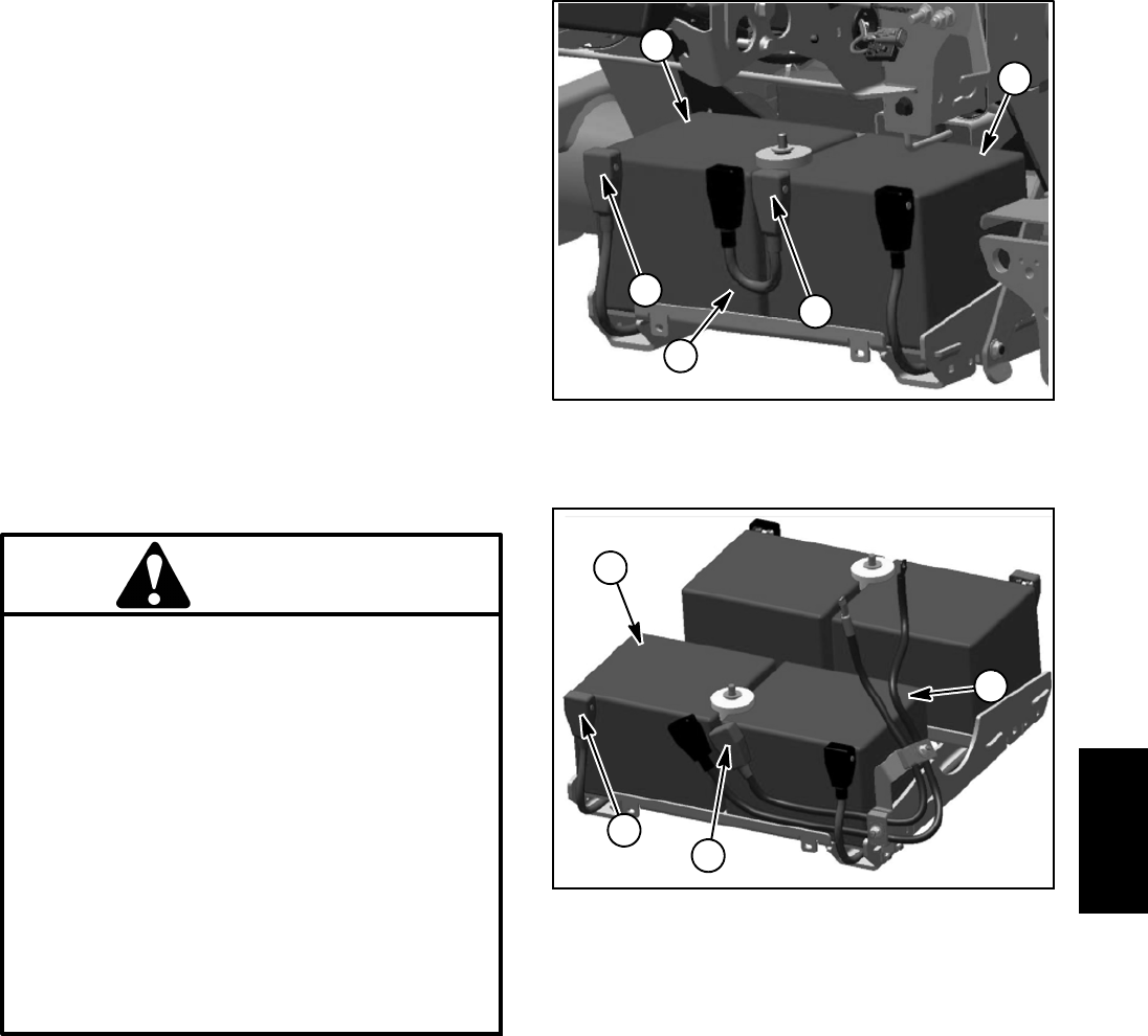
1. LH rear battery
2. RH rear battery
3. Positive terminal
Figure 87
1
2
3
3
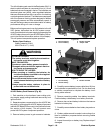
4. Carefully removebatteryjumper cable(item16) from
front batteries to open battery circuit. Do not allow tools
or vehicle components to complete th e battery circuit
during cable r emoval.
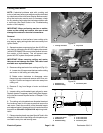
5. Remove remaining cables from battery terminals.
Position battery cables away from battery terminals.
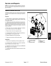
6. Remove hex nut and battery hold down that secure
batteries to battery tray.
7. Carefully remove batteries from battery tray and ma-
chine.
8. Ifbattery cableremoval isneeded,noterouting ofca-
bles for installation purposes before removing cables
from machine.
9. Inspect foam strips on battery tray. Replace strips if
damaged.
Electrical
System