


Reelmaster 5010- H Hydraulic SystemPage 4 - 33
NOTE: If machine is equipped with optional
CrossTrax
TM
AWD, reverse relief pressure test ports
are located on CrossTrax
TM
hydraulic manifold.
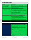
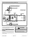
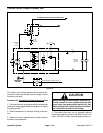
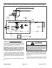
3. Thoroughly clean traction circuit test port on hydrau-
lic tube for direction to be checked (Fig. 27). Connect a
5000 PSI (350 bar) pressure gauge to test port.
4. After installing tester, start engine and run a t low idle
speed. Check for any hydraulic leakage from t est con-
nections and correct before proceeding with test.
5. Make sure hydraulic oil is at normal operating tem-
perature by operating the machine under load for
approximately ten (10) minutes.
6. Sit on seat and increase engine speed to high idle
speed (3000 RPM).
7. Apply brakes and slowly depress the traction pedal
in the direction to be tested (forward or reverse). While
pushing traction pedal down, carefully watch the pres-
sure gauge needle. As the traction relief valve lifts, the
gauge needle will momentarily stop. Traction system
pressure as the relief valve opens should be:
Approximately3625 PSI(250 bar)inboth forward
(R3) and reverse (R4)
NOTE: If traction pedal continues to be pressed after
the relief valve has opened, system pressure may in-
crease higher than relief pressure.
8. When relief pressure has been identified, release
traction pedal, stop engine and record test results.
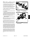
NOTE: Forward (R3) and reverse (R4) relief valves are
identical. Relief valves can be switched in piston (trac-
tion)pumptohelpinidentifyingafaultyreliefvalve.
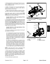
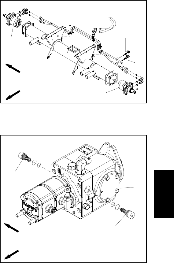
9. If traction pressure problem occurs in one direction
only, interchange the relief valves in the piston (traction)
pump(Fig. 28)to seeifthe problemchangesto theother
direction. Clean or replace valves as necessary. These
cartridge type valves are factory set, and are not adjust-
able.If tractionreliefpressure islow andreliefvalves are
in good condition, piston (traction) pump and/or wheel
motors should be suspected of wear and inefficiency.
10.After testing is completed, make sure that engine is
stopped and then relieve hydraulic system pressure
(See Relieving Hydraulic System Pressure in the Gen-
eral Information section of this chapter). Remove pres-
sure gauge from machine and install dust cap to test
port.
1. RHwheel motor
2. LH wheel motor
3. Forward test port
4. Reverse test port
Figure 27
FRONT
RIGHT
2WD MACHINE SHOWN
2
3
4
1
1. Piston (traction) pump
2. Reverse relief valve (R4)
3. Forward relief valve (R3)
Figure 28
2
3
1
FRONT
RIGHT
Hydraulic
System