


Reelmaster 5010- H Hydraulic SystemPage 4 - 93
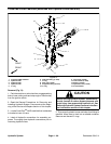
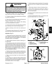
3. Using a spanner wrench, rotate head clockwise until
theedge ofthe retainingring appearsin thebarrel open-
ing. Insert a screwdriver under the beveled edge of the
retainingring tostart theretaining ringthrough theopen-
ing.Rotatetheheadcounter-clockwisetoremovere-
taining r ing from barrel and head.
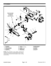
4. Remove plugs from ports. Extract shaft, head and
piston by carefully twisting and pulling o n the shaft.
IMPORTANT: D o not clamp vise jaws against the
shaft surface. Clamp on the clevis ONLY.
5. Mount shaftsecurely ina viseb y clampingon thecle-
vis of the shaft. Remove lock nut and piston from the
shaft. Carefully slide head off the shaft.
6. Taking care to not scratch or damage the piston, re-
move wear ring, BP seal and O- ring from the piston.
7. Taking care to not scratch or damage the head, re-
move O- ring, back- up washer, dust seal and BS seal
from the head.
8. Discard removed seals and O- rings.
Inspection
CAUTION
Useeye protectionsuch asgoggles whenusing
compressed air to clean lift cylinder compo-
nents.
1. Wash all lift cylinder components in solvent. Dry
parts with compressed air.
2. Inspect internal surface of barrel for deep scratches,
out- of- roundness and bending.
3. Inspect head, shaft and piston for excessive pitting,
scoring and wear.
4. Replace lift cylinder ifinternal componentsare found
to be worn or damaged.
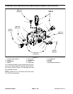
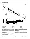
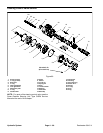
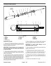
Assembly (Fig. 76)
1. Make sure all lift cylinder parts are clean before as-
sembly.
2. Coat new O- rings, back- up washer and other seals
with clean hydraulic oil.
A. Carefully install wear ring, BP seal and O- ring to
the piston.
B. Carefully install back- up washer, O - ring, dust
seal and BS seal to the head.
IMPORTANT: Do not clamp vise jaws against the
shaft surface. Clamp on the clevis ONLY.
3. Mount shaftsecurelyin aviseby clampingonthe cle-
vis of the shaft.
A. Coat shaft with clean hydraulic oil.
B. Slideheadassemblyontotheshaft.
C. Install piston assembly onto the shaft and secure
with lock nut. Torque lock nut 40 ft-lb (54 N-m).
D. Remove shaft assembly from the vise.
IMPORTANT: Prevent damage when clamping the
hydraulic cylinder into a vise; clamp on the clevis
end o f the barrel ONLY.
4. Mount barrel securely in a vise by clamping on the
clevis end of the barrel.
IMPORTANT: When installing the head into the bar-
rel, pay careful attention to the retaining ring slot in
thebarreltoinsurethat thepistonand heads eals do
not lodge in the slot.
5. Coat all internal parts with a light coat of clean hy-
draulic oil. Slide piston, shaft and head assembly into
the barrel being careful not to damage the seals.
6. Secure head in barrel by installing retaining ring.
A. Align retaining ring hole in the head with the a c-
cess slot in the barrel.
B. Insert the retaining ring hook into the hole and ro-
tate head clockwise until the retaining ring is com-
pletely pulled into the barrel and the ring ends are
covered.
Hydraulic
System