


Reelmaster 5010- H Hydraulic SystemPage 4 - 83
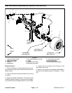
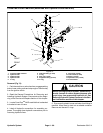
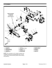
Removal (Fig. 69)
1. Park themachine on alevel surface,engage parking
brake, lower cutting units and stop engine. Remove key
from the ignition switch.
2. Read the General Precautions for Removing and
Installing Hydraulic System Components at the begin-
ning of the Service and Repairs section of this chapter.
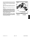
3. Locate hydraulic lift control manifold that is attached
to frame bracket under the front platform.
4. Label all hydraulic connections f or assembly pur-
poses. Thoroughly clean hydraulic connections prior to
loosening hydraulic lines.
CAUTION
Before opening hydraulic system, operate all hy-
draulic controls to relieve system pressure and
avoid injury from pressurized hydraulic oil. See
Relieving HydraulicSystem Pressurein the Gen-
eral Information section of this chapter.
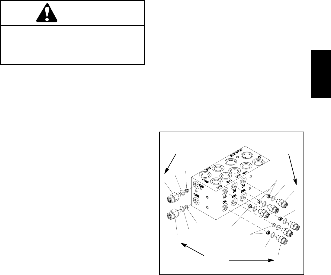
5. Disconnect hydraulic hosesand tubesfrom fittingsin
manifold. Allow lines to drain into a suitable container.
Remove and discard O- rings.
6. Put caps or plugs on disconnected hydraulic lines
and fittings to prevent contamination.
7. Label all solenoid coil wire harness leads for as-
sembly purposes. Unplug wire harness leads fromsole-
noid coils on manifold.
8. Remove two (2) flange head screws that secure
manifold to machine frame.
9. Remove lift control manifold from machine.
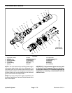
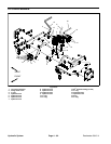
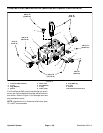
IMPORTANT: A flow control orifice is placed be-
neath several hydraulic fittings on the lift control
manifold (Fig. 70). The lift manifold uses three (3)
different orifice sizes. If fittings are removed from
manifold and an orifice is in themanifold port, make
sure to remove orifice and label its position for as -
sembly purposes.
10.Ifnecessary,removehydraulicfittings frommanifold.
Discard any removed O- rings. Locate, retrieve and la-
bel orifice from manifold ports (if equipped).
Installation (Fig. 69)
1. If fittings were removed from manifold:
A. Lubricate new O- rings with clean hydraulic oil.
Install lubricated O- rings on fittings.
IMPORTANT: When installing orifice in manifold
(Fig. 70), make sure that orifice is flat in the base
of the fitting cavity. Manifold damage is possible
if the orifice is cocked in the cavity.
B. For manifold ports with orifice, place correct ori-
fice in port with the orifice slot facing out.
C. Install fittings into manifold (see Hydraulic Fitting
Installation in the General Information section of this
chapter). Torque fittings to torque values identified in
Figure 70.
2. Position lift control manifold to frame. Install two (2)
flange head screws but do not fully tighten.
3. Remove caps and plugs from hydraulic lines and fit-
tings.
4. Lubricate and install new O- ring(s) on manifold fit-
tings. Connect and tighten hydraulic lines to hydraulic
manifold fittings (see Hydraulic Hose and Tube Installa-
tion in the General Information section of this chapter)
5. Secure hydraulic manifold to frameby tighteningtwo
(2) flange head screws.
6. Connect wire harness leads to solenoid coils on
manifold using labels placed during removal.
7. Check oil level in hydraulic reservoir and add correct
oil if necessary.
8. Follow Hydraulic System Start- up procedures (see
Hydraulic System Start- up in this section).
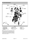
1. Fitting (2 used)
2. O-ring
3. Orifice (0.046)
4. Orifice (0.028)
5. Fitting (6 used)
6. Orifice (0.055)
Figure 70
4
1
2
5
3
1
2
3
4
2
2
6
6
5
(14 N-m)
10 ft-lb
(14 N-m)
10 ft-lb
(14 N-m)
10 ft-lb
Hydraulic
System