


Reelmaster 5010- H
Cutting Units
Page 7 - 33
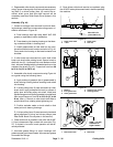
3. From the roller tube end with only the inner seal
installed, carefully install the roller shaft into the roller
tube. Make sure that seals are not damaged as shaft is
installed.
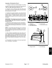
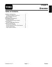
4. Install new bearing and outer seals into second end
of roller tube:
A. Position a second new bearing t o roller shaft and
tube. Position washer (see Special Tools in this
chapter) on bearing to allow pressing on both inner
and outer bearing races simultaneously.
B. Use washer and bearing/outer seal tool (see
SpecialToolsin thischapter)withasoftfacehammer
to fully seat bearing (Fig. 42). After bearing installa-
tion, m ake sure that shaft freely rotates and that no
binding is detected. If necessary, lightly tap bearing
and/or shaft ends to align shaft and bearings. Re-
move washer from roller.
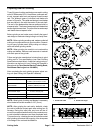
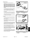
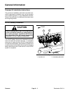
C. Apply a small amount of grease around the lip of
both outer seals.
D. Carefully install first outersealintorollertube
making sure that seal lip (and garter spring) faces
end oftube. Use bearing/outer sealtool (see Special
Tools in this chapter) and soft face hammer to lightly
seat seal (Fig. 43). Make sure that shaft and bear-
ings still freely rotate after seal installation.
E. Using the same process, install second outer
sealmaking suretonot crushtheinstalledouterseal.
Again, make sure that shaft a nd bearings still freely
rotate.
IMPORTANT: Make sure that all grease is removed
from shaft threads to prevent bearing lock nut loos-
ening.
5. Thoroughly clean threads on both ends of roller
shaft.
NOTE: If original bearing lock nut(s) are being used,
apply Loctite #242 (or equivalent) to threads of lock
nut(s).
6. Install bearing lock nut onto each end of the roller
shaft. Make sure that outer seals are not damaged dur-
ing nut installation. Torque lock nuts from 50 to 60 ft-lb
(68to81N-m).
7. If set screw was removed from either end of roller
shaft, apply Loctite#242 (or equivalent) tothreads ofre-
moved set screw and install into roller shaft. Tighten set
screw until it bottoms in shaft and is recessed in shaft.
IMPORTANT: When roller assembly is installed to
cutting deck, make sure that grease groove in each
roller mount aligns with the grease hole in each end
of ro ller shaft.
NOTE: After roller is installed to cutting deck, lubricate
roller grease fittings, rotate roller to properly distribute
grease in bearings and clean excess grease from roller
ends. A properly assembled roller should rotate with
less than 5 in- lbs (0.68 N- m) resistance.
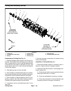
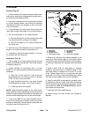
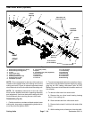
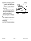
1. Roller tube
2. Inner seal
3. Bearing
4. Outer seal
5. Bearing/outer seal tool
Figure 41
3
4
2
1
5
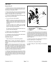
1. Roller tube
2. Roller shaft
3. Inner seal
4. Bearing
5. Washer
6. Bearing/outer seal tool
Figure 42
3
4
2
1
5
6
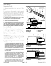
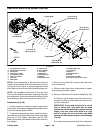
1. Roller tube
2. Roller shaft
3. Inner seal
4. Bearing
5. Outer seal
6. Bearing/outer seal tool
Figure 43
3
4
2
1
5
6
Cutting
Units