


Reelmaster 5010- HPage 5 - 92Electrical System
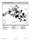
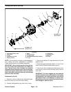
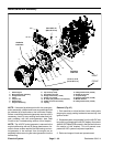
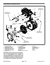
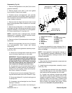
Motor/Generator Assembly
Figure 97
1. Diesel engine
2. Motor/generator assembly
3. Flange head screw
4. Collar
5. Coupler hub
6. Woodruff key
7. Engine bellhousing
8. Cap screw (2 used)
9. Flat washer (2 used)
10. Flange head screw (7 used)
11. Flange nut (2 used)
12. R-clamp (for generator wire harness)
13. Clamp (for fuel return hose)
14. Caplug
15. Flange head screw (6 used)
16. Dowel pin (2 used)
17. Coupler flange
18. Socket head screw (3 used)
19. Muffler bracket
20. Flange head screw (4 used)
3
9
10
11
5
4
13
2
6
8
1
7
12
14
15
16
17
18
19
20
FRONT
RIGHT
50 to 60 ft- lb
(68to81N-m)
25 to 31 ft-lb
(34to42N-m)
Antiseize
Lubricant
Antiseize
Lubricant
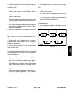
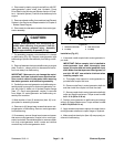
NOTE: If electrical problems exist with the motor/gen-
erator assembly, afaultshouldhaveoccurredthat would
be indicated by a fault code on the InfoCenter Display.
Before considering that motor/generator service work is
necessary, check for any existing fault codes that indi-
cate problems with the motor/generator (see Fault
Codes in the Troubleshooting section of this chapter).
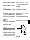
NOTE: The 48 VDC motor/generator is secured to the
engine bellhousing with six (6) flange head screws. Ac-
cess to these screws requires the bellhousing and mo-
tor/generator to be removed from the engine as an
assemblybeforeremovingthemotor/generatorfromthe
bellhousing.
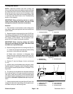
Removal (Fig. 97)
1. Park machine on a level surface, lower cutting units,
stop engine, apply parking brake and remove key from
ignition switch.
2. Separate system components from the 48 VDC bat-
tery pack by unplugging the 48 VDC battery disconnect.
(see48 VDCBatteryDisconnect intheGeneralInforma-
tion section of this chapter). This will prevent unex-
pected 48 VDC system component operation.
3. Raise and support hood and operator seat.