


Reelmaster 5010- HPage 5 - 72Electrical System
Oil Pressure Switch
The engine oil pressure switch is a normally closed
switch that opens with pressure during normal engine
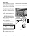
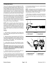
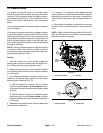
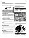
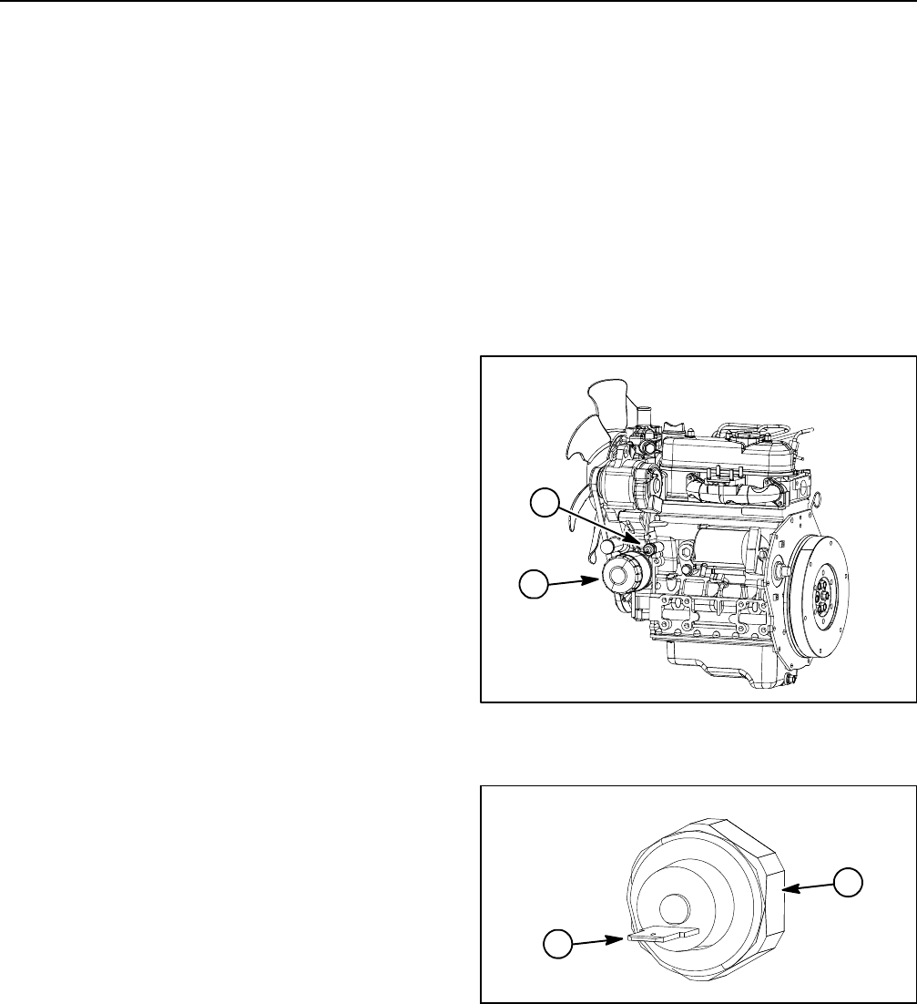
operation. The oil pressure switch is located on the en-
gine near the oil filter (Fig.74). The Toro Electronic Con-
troller (TEC) monitors the operation of the oil pressure
switch.
The oil pressure switch should open at approximately 8
PSI (0.56 kg/cm
2
).
If low engine oil pressure allows the oil pressure switch
to close during engine operation and the TEC controller
detects a low oil pressure input for ten (10) seconds, the
engine will be shutoff by thecontroller.The operator will
see an advisory (advisory #169) on the InfoCenter dis-
play explaining that low engine oil pressure has caused
the engine shutdown.
NOTE: Afaulty oilpressure switchor faulty wiringto the
oil pressure switch could cause a closed circuit that
would lead to engine shutdown with an InfoCenter dis-
play identifying Advisory #169.
Testing
1. Park the machine on a level surface, engage the
parking brake, lower the cutting units and stop the en-
gine. Remove the key from the ignition switch.
2. Raise a nd support hood. Locate oil pressure switch
on engine and disconnect the wire harness connector
from the switch.
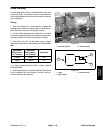
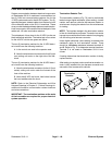
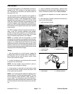
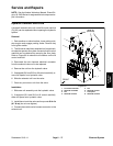
3. Use a digital multimeter to measure continuity be-
tween the oil pressure switch terminal and the switch
base (ground connection) (Fig. 75).
A. With the engine not running, the oil pressure
switch should beclosed so thereshou ld be continu-
ity between the switch terminal and the switch base
(0 ohms).
B. With the engine running, the oil pressure switch
should be open so there should not be continuity
between the switch terminal and the switch base (in-
finite ohms).
4. Replace the oil pressure switch if testing determines
that the switch is defective.
5. If testing of o il pressure switch determines that
switch operation is normal and the InfoCenter display is
identifying low engine oil as the cause of engine shut-
down, check for faulty wire in the oil pressure switch cir-
cuit.
6. After testing is completed, connect the wire harness
connector to the oil pressure switch. Lower and secure
hood.
NOTE: Refer to Kubota Workshop Ma nual, Diesel En-
gine, 05- E4B Series for information regarding engine
lubrication system and testing.
Figure 74
1. Oil pressure switch 2. Oil filter
2
1
1. Switch terminal 2. Switch base
Figure 75
2
1