


Reelmaster 5010- H Page 5 - 93 Electrical System
4. Disconnect hydraulic pump drive shaft from 48 VDC
motor/generator o utput shaft (see Hydraulic Pump
Drive Shaft in the Service and Repairs section of Chap-
ter4 - HydraulicSystem). Positiondriveshaft awayfrom
engine.
5. Remove exhaustmufflerfrommachine (seeExhaust
System in the Service and Repairs section of Chapter 3
- Kubota Diesel Engine).
6. Disconnect wire harness connector from motor/gen-
erator assembly.
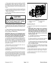
CAUTION
Support motor/generator and bellhousing as-
sembly when removing it to prevent it from fal-
ling and causing personal injury. Assembly
weighs approximately 69 pounds (31 kg).
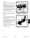
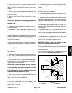
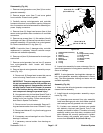
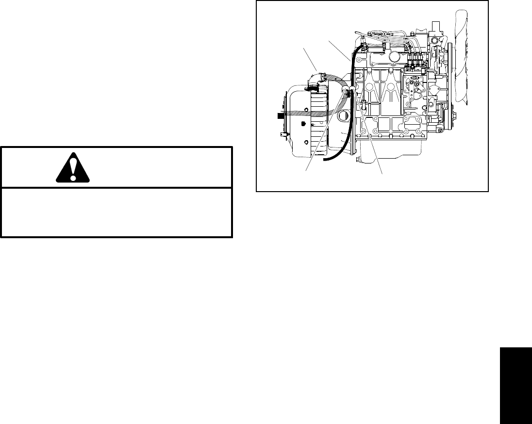
7. For assembly purposes, note locations of r- clamps
on bellhousing (Fig. 98). Support motor/generator and
bellhousingto prevent the assembly from falling or shift-
ing.
8. Remove fasteners that secure bellhousing to engine
plate. Position r- clamps with wire harness and fuel re-
turn hose away from bellhousing.
IMPORTANT: Make sure to not damage the motor/
generator,fuellines, hydraulichoses, electricalhar-
ness, control cables or o ther parts while removing
the motor/generator and bellhousing assembly.
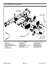
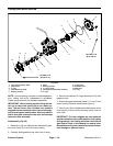
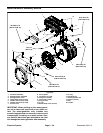
9. Carefully move motor/generator and bellhousing as-
sembly away from engine so that motor/generator cou-
pler hub (item 5) slides out of flywheel coupler flange
(item 17). Once motor/generator coupler is removed
from flange, lift motor/generator and bellhousing as-
sembly from machine.
10.Note location of two (2) dowel pins (item 16) in en-
gine plate for assembly purposes.
11.Remove six (6) flange head screws that secure mo-
tor/generator to bellhousing. Remove motor/generator
from bellhousing.
12.If necessary, remove flange head screw and spacer
that secure motor/generator coupler hub to motor/gen-
erator input shaft. Use suitable puller to remove coupler
hub from motor/generator shaft. Locate and retrieve
woodruff key from motor/generator shaft.
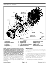
1. Generator connector
2. R-clamp
3. Fuel return hose
4. R-clamp
Figure 98
3
2
1
4
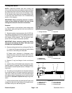
Installation (Fig. 97)
1. If removed,install coupler hub tomotor/generator in-
put shaft:
IMPORTANT: Before coupler hub is installed to
motor/generator input shaft, thoroughly clean
tapers of coupler hub and motor/generator input
shaft.Make surethat tapersare freeof grease,oil
and dirt. DO NOT use antiseize lubricant when
installing coupler hub.
A. Thoroughly clean tapers on motor/generator in-
put shaft and coupler h ub bore.
B. Place woodruff key in motor/generator shaft slot
and then install the coupler hub onto the shaft.
C. Secure couplerhub to motor/generator shaft with
collar and flange head screw. Torque screw from 25
to 31 ft- lb (34 to 42 N-m).
2. Position motor/generator to bellhousing and secure
with six (6) flange head screws. Torque screws from 50
to 60 ft- lb (68 to 81 N-m).
3. Apply antiseize lubricantto splines of coupler hub on
motor/generator shaft and coupler flange on flywheel.
4. Make sure that dowel pins (item 16) are properly po-
sitioned in bellhousing.
Electrical
System