


Reelmaster 5010- H Hydraulic SystemPage 4 - 61
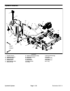
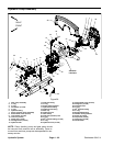
Disassembly (Fig. 53)
1. Park themachine on alevel surface,engage parking
brake, lower cutting units and stop engine. Remove key
from the ignition switch.
2. Remove components from piston (traction) pump
control assembly as needed using Figures 53 and 54 as
guides.
Assembly (Fig. 53)
IMPORTANT: To prevent traction neutral switch
(item 17) damage, make sure that no pump control
components contact switch through entire piston
(traction) pump control arm movement.
1. Install removed components to piston (traction)
pump control assembly using Figures 53 and 54 as
guides along with the following:
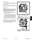
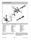
A. If traction neutral switch (item 17) was removed
from pump plate, adjust location of switch so that
there isfrom 0.094” to 0.100” (2.4 to 2.5 mm) clear-
ance betweenthe head ofneutral switch andthe pis-
ton (traction) pump lever (Refer to Traction Neutral
Switch in the Adjustments section of Chapter 5 -
Electrical System for additional neutral switch infor-
mation).
2. After piston (traction) pump control assembly has
been installed, make sure that the piston pump is ad-
justed for the neutral position so that the machine does
not move or creep when the traction pedal is in neutral
(see Traction Unit Operator’s Manual).
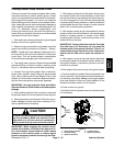
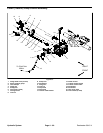
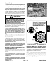
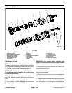
1. Pump lever
2. Traction neutral switch
3. Traction control cable
4. Cable jam nut
5. Cable rod end
Figure 54
1
5
3
2
4
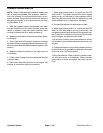
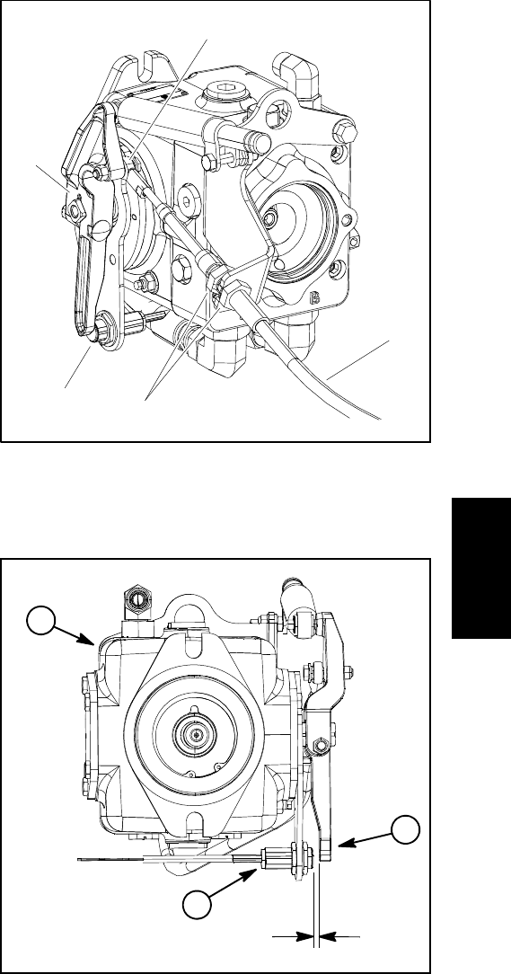
Figure 55
1. Piston pump
2. Pump lever
3. Traction neutral switch
2
1
3
0.094” to 0.100”
(2.4 to 2.5 mm)
Hydraulic
System