


Reelmaster 5010- H
Cutting Units
Page 7 - 23
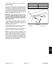
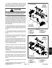
4. If cutting unit is equipped with a weight on LH side
plate, remove the two (2) flange nuts securing the
weight to the side plateand remove weight from thecut-
ting unit. Remove and discard O- ring from weight.
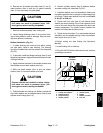
CAUTION
Contact with the reel, bedknife or other cutting
unit parts can result in personal injury. Use
heavy gloves when removing the cutting reel.
5. If cuttingunit isequipped withan optionalgroomer or
rear roller brush, remove components for those options
from left hand side plate of cutting unit. See Service and
Repairs section of Chapter 9 - Groomer for information
on groomer disassembly. See Rear Roller Brush and
Rear Roller Brush Drive System in the Service and Re-
pairs section of thischapter for information onrear roller
brush disassembly.
6. Remove the bedbar pivot bolt and washers from the
LH side plate. Note location of plastic and steel washers
for assembly purposes (see Bedbar Assembly in this
section).
7. Loosen fasteners that securefront and rear rollers to
LH side plate (see Front Roller and Rear Roller in this
section).
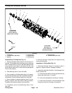
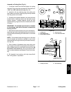
8. Remove cap screw and flat washer that secure rear
grass shield to LH side plate (Fig. 29 for 7” cutting units
or Fig. 30 for 5” cutting unit).
9. Remove fasteners that secure frame spacer, wash-
er(s)and carrierframeto LHsideplate( Fig. 29for7” cut-
ting units or Fig. 30 for 5” cutting unit). Note the number
of washers that exist between LH side plate and carrier
frame for assembly purposes.
10.Support cutting reel to keep it from shifting or falling.
NOTE: Side plates on 5” cutting reel attach to cutting
unit frame with two (2) shoulder bolts and flange nuts.
Sideplates on7”cutting reeluse three(3)shoulder bolts
and flange nuts.
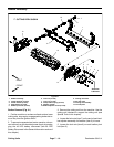
11.Remove shoulderbolts(item8) andflange nuts(item
24) that secure the LH side plate to cutting unit frame.
12.Carefully remove the LH side plate from the reel
shaft, rollers, bedbar, carrier frame and cutting unit
frame. Locate and remove flat wire spring (item 14 in
Fig. 28).
13.Carefully slide thecutting reel assemblyfrom the RH
side plate.
14.Inspect and service cutting reel assembly (see Cut-
ting Reel Assembly Service in this section).
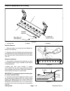
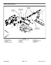
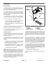
1. Carrier frame
2. Washer
3. Support tube
4. Frame spacer
5. Flat washer
6. Cap screw
7. Flange head screw
8. Rear grass shield
9. LH side plate
Figure 29
1
3
2
6
8
4
7
5
27 to 33 ft-lb
(37 to 44 N-m)
Loctite #242
9
4
7” CUTTING REEL
15 to 19 ft-lb
(20 to 25 N-m)
Lubricant
Antiseize
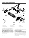
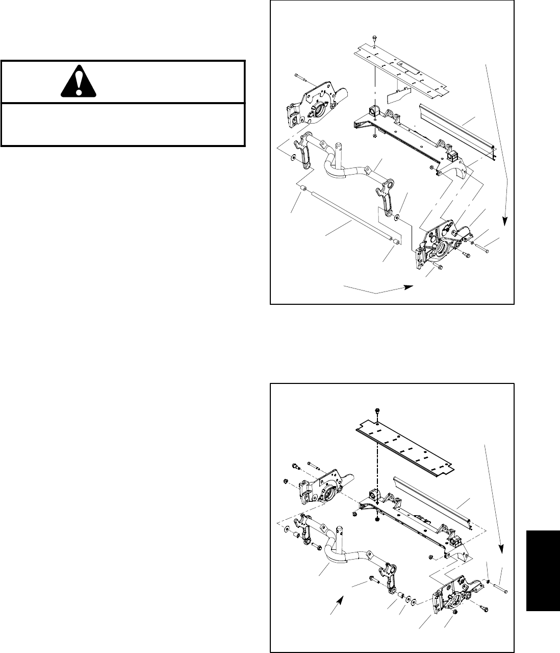
1. Carrier frame
2. Washer
3. Frame spacer
4. Flange head screw
5. Flange nut
6. LH side plate
7. Rear grass shield
8. Flat washer
9. Cap screw
Figure 30
1
3
2
6
8
7
5
9
4
27 to 33 ft- lb
(37 to 44 N-m)
15 to 19 ft-lb
(20to25N-m)
Lubricant
Antiseize
5” CUTTING REEL
Cutting
Units