


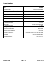
Reelmaster 5010- H Page 3 - 15 Kubota Diesel Engine
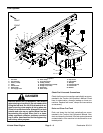
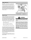
Engine Removal (Fig. 10)
1. Park machine on a level surface, lower cutting units,
stop engine and remove key from the ignition switch.
Chock wheels to keep the m achine from moving.
2. Disconnect negative (- ) and thenpositive (+) battery
cables from the12 volt battery at the rear of the machine
(see 12 VDC Battery Service in the Service and Repairs
section of Chapter 5 - Electrical System).
3. Open and support hood.
4. Separate system components from the 48 VDC bat-
tery pack by unplugging the 48 VDC battery disconnect.
(see 48 VDC Battery Disconnect in the General Infor-
mation section of this chapter). This will prevent unex-
pected 48 VDC system component operation.
5. Remove air c leaner from machine (see Air Cleaner
Assembly in this section).
6. Remove exhaust muffler from machine (see Ex-
haust System in this section).
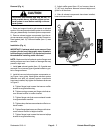
CAUTION
Do not open radiator cap or drain coolant if the
radiator or engine is hot. Pressurized, hot cool-
ant can escape and cause burns.
Ethylene-glycol antifreeze is poisonous. Dis-
pose of coolant properly, or store itin aproperly
labeled container away from children and pets.
7. Drain radiator into a suitable container either by us-
ing the draincock onthe left side of the radiator or bydis-
connecting the lower radiator hose from the radiator.
Make sure that drain container is lar ge enough to hold
cooling system contents (see Specifications in this
Chapter).
IMPORTANT: Follow all local codes and regula-
tions when recycling or disposing engine coolant.
8. Disconnect hoses from engine:
A. Loosen clamps and remove upper and lower ra-
diator hoses from the engine.
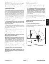
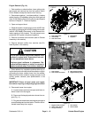
B. Disconnect fuel supply and return hoses from en-
gine (Fig. 11).
C. Plug disconnectedhoses andengine openings to
prevent leakage andcontamination. Positiondiscon-
nected hoses away from engine.
Figure 11
1. Fuel supply hose
2. Hose clamp
3. Fuel return hose
4. Hose clamp
5. Separator
FRONT
2
3
1
5
4
2
Figure 12
1. Fuel actuator
2. Fuel actuator connector
3. Wire harness ground
4. Negative battery cable
1
4
3
2
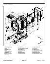
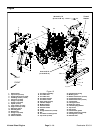
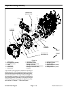
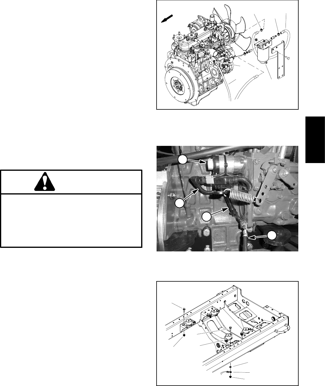
Figure 13
1. Engine mount (4 used)
2. Screw (2 per mount)
3. Nut (2 pe r mount)
4. Lock washer
5. Ground cable
1
2
4
5
3
2
3
Kubota Diesel
Engine