


Reelmaster 5010- H GroomerPage 8 - 17
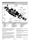
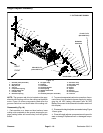
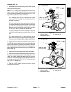
Assembly (Fig. 18)
1. Assemble height adjuster using Figure 18 asa guide
noting the following items:
NOTE: On 7” cutting units, the ball joint rod on the cut-
ting unit motor side is longer that the ball joint rod used
on the groomer drive side of the cutting unit. On 5” cut-
ting units, the ball joint rods are identical.
A. If bushing (item 10) was removed from upper
ramp, press new bushing into housing fully to the
shoulder in the bore.
B. If jam nuts (item 4) were removed from ball joint
rod, apply antiseize lubricant to threads of rod where
jam nuts will be positioned. Install jam nuts so that
distance from top of ball joint rod to bottom of lower
nut is from 3.190” to 3.310” (8.1 to 8.4 cm).
C. Apply antiseize lubricant to threads of ball joint
rod before installing groomer adjuster (item 12) onto
rod.
D. If detent spring (item 1 3) was removed, secure
detentspring toupperramp withwasher headscrew.
Torque screw from 30 to 40 in-lb ( 3.4 to 4.5 N- m).
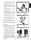
2. Apply antiseize lubricant to shoulder area of shoul-
der bolt that secures ball joint rod to groomer plate and
apply Loctite#242 (or equivalent) tothreads of shoulder
bolt. Position spacer between ball joint rodand groomer
plate.Install shoulder bolt and torquefrom 17to 21ft- lb
(23to28N-m).
3. Check groomer reel height and adjust as needed.
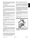
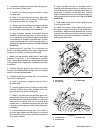
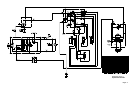
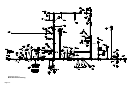
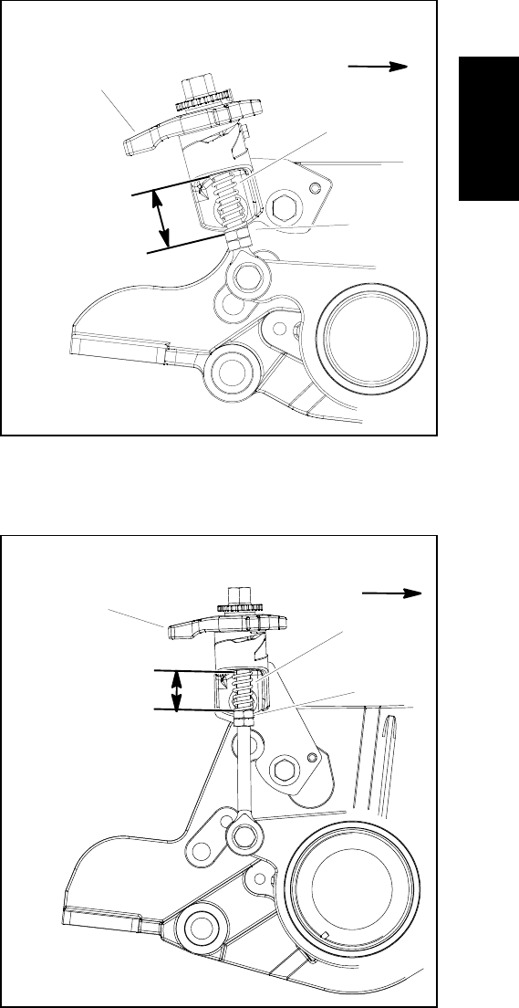
4. After groomer height has beenadjusted, adjustloca-
tion of jam nuts so compression spring length is from
1.320” to 1.440” (3.4 to 3.6 mm) when the groomer
handleis inthe disengagedposition (handletoward rear
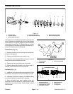
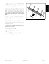
of cutting unit) (shown in Fig. 19 For 5” cutting unit and
Fig. 20 For 7” cutting unit).
5. Plug the 48 VDC battery disconnect back in before
operating the machine.
1. Groomer h andle
2. Compression spring
3. Upper jam nut
Figure 19
1.320” to 1.440”
(3.4 to 3.6 mm)
FRONT
1
2
3
5” CUTTING UNIT
Figure 20
1
2
3
1.320” to 1.440”
(3.4 to 3.6 mm)
1. Groomer h andle
2. Compression spring
3. Upper jam nut
FRONT
7” CUTTING UNIT
Groomer