


Reelmaster 5010- H Page 5 - 97 Electrical System
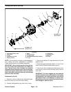
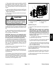
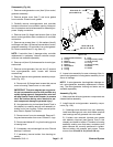
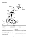
Disassembly (Fig. 99)
1. Remove motor/generator cover (item 3) from motor/
generator assembly.
2. Remove access cover (item 7) and cover gasket
from controller. Discard cover gasket.
3. Carefully remove motor/generator and controller
harness connectors from controller opening. Note posi-
tionof connectorsand wireharnessesfor assemblypur-
poses. Unplug connectors.
4. Remove three (3) flange head screws (item 4) that
secure motor/generator stator conductors to controller
connectors.
5. Remove cap screws (item 11), flat washers (item 9)
and flange nuts (item10) thatsecure controller tomotor/
generator assembly. Lift controller from motor/genera-
tor. Remove and discard O- ring (item 15).
NOTE: If controller (item 1) damage exists, controller
replacement is necessary. Internal controller compo-
nents are n ot available separately.
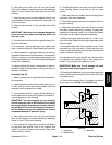
6. Remove nut (item 19) thatsecures fan to motor/gen-
erator shaft.
7. Remove motor/generator f an and two (2) spacers
from motor/generator shaft. Locate and retrieve
woodruff key.
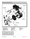
8. Remove internal motor/generator assembly compo-
nents (Fig. 100):
A. Remove six (6) flange head screws that secure
cover to housing. Leave cover on rotor shaft.
IMPORTANT: The rotor magnets are very power-
ful and can cause the rotor to shift position very
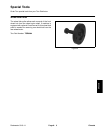
rapidly during removal. Use generator rotor tool
set (see Special Tools in this chapter) to remove
rotor. Be cautious during rotor removal to pre-
vent component damage or personal injury.
B. Use generator rotor tool set (see Special Tools in
this chapter) to carefully remove rotor assembly in-
cluding cover from housing. Follow removal proce-
dure listed in Special Tool section.
C. Remove cover from rotor assembly. Remove O-
rings andwave washer from cover.Discard O- rings.
D. Removeand discardO- ringfromhousinggroove
in bearing bore.
E. Ifnecessary, removebearingsfrom rotor.Discard
bearings if removed.
F. If necessary, remove isolator from housing as-
sembly.
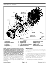
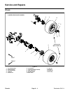
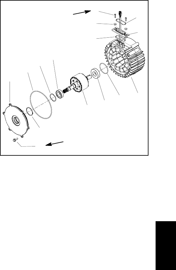
1. Housing/stator assembly
2. O-ring
3. Bearing
4. Rotor assembly
5. Bearing
6. Wave washer
7. O-ring
8. O-ring
9. Cover
10. Flange screw (6 used)
11. Screw ( 2 used)
12. O-ring
13. Spacer (2 used)
14. Isolator
15. Gasket
Figure 100
170 to 190 in-lb
(19.3 to 21.4 N-m)
2
3
6
8
9
10
1
5
7
4
11
12
13
14
15
35 to 45 in-lb
(4.0 to 5.0 N-m)
9. Inspect rotor assembly for wear or damage. Also, in-
spect motor/generator housing/stator assembly for evi-
dence of damage.
NOTE: If motor/generator housing/stator damage ex-
ists, motor/generator assembly replacement is neces-
sary. The motor/generator housing and stator are not
available separately.
Assembly (Fig. 99)
1. Make sure that all motor/generator components are
cleaned before assembly.
2. Install internal motor/generator assembly compo-
nents (Fig. 100):
A. If bearings were removed from rotor assembly,
install new bearings onto rotor shaft. Make sure that
new bearings are fully pressed onto rotor shaft.
B. If isolator was removed, lubricate new gasket
with dielectric lubricant (see Special Tools in this
chapter) and install to isolator. Fit isolator to housing
assembly making sure that stator conductors and
stator harness are correctly positioned in isolator.
Secure isolator with spacers and screws. Torque
screws from 35 to 45 in-lb (4.0 to 5.0 N-m).
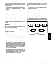
Electrical
System