


Reelmaster 5010- H Hydraulic SystemPage 4 - 37
3. Raise and prop operator seat to allow access to hy-
draulic pump assembly.
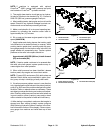
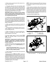
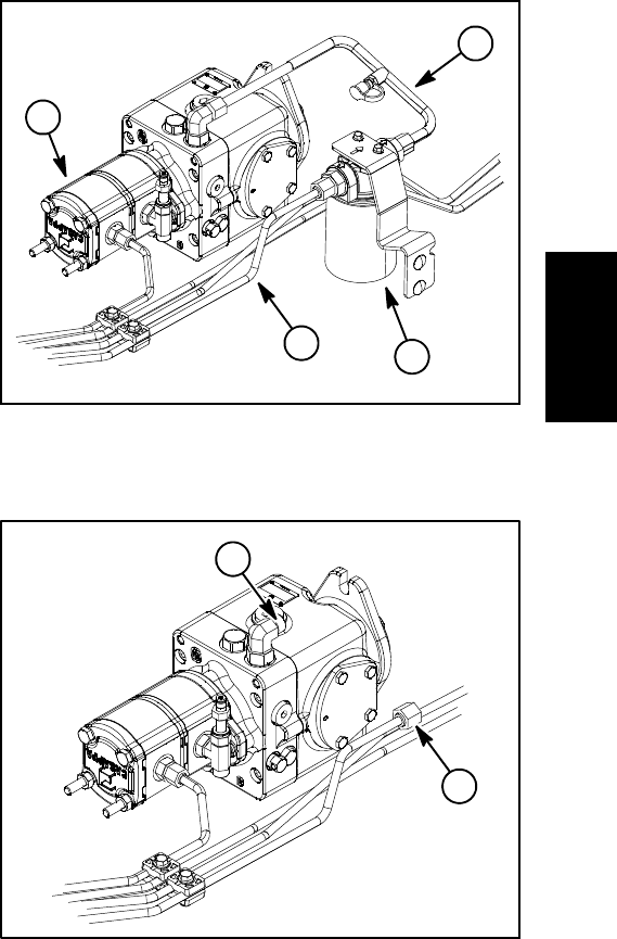
4. Thoroughly clean the ends of the hydraulic tubes
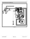
connected to the oil filter and piston pump inlets (Fig.
33). Disconnect hydraulic tubes from oil filter inlet and
piston pump inlet. Remove two (2) flange head screws
that secure oil filter adapter to frame. Remove oil filter
assembly and hydraulic tube from machine.
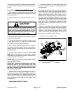
IMPORTANT: Make sure that the oil flow indicator
arrow on the flow meter is showing that the oil will
flow from the hydraulic tube, through the tester and
into the piston (traction) pump.
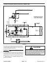
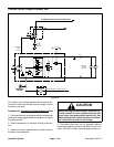
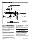
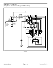
5. Install tester with pressure gauge and flow meter in
place of the removed oil filter assembly and hydraulic
tube (Fig. 34). Connect tester inlet hose to the h ydraulic
tube. Connect the tester outlet hose to the piston (trac-
tion) pumpfitting. Make sure the flow control valve on
tester is fully open.
6. Make sure that the traction pedal is in neutral, the
steering wheel is stationary and the parking brake is en-
gaged.
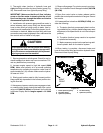
7. Start engine and run at idle speed. Check for any hy-
draulic leakage from test connections and correct be-
fore proceeding with test.
8. Make sure hydraulic oil is at normal operating tem-
perature by operating the machine under load for
approximately ten (10) minutes.
9. Increase engine speed to high idle speed (3000
RPM). Use InfoCenter Display to verify that engine
speed is correct.
IMPORTANT: The gear pump is a positive displace-
ment type. If pump flow is completely restricted or
stopped, damage to the pump, tester or other com-
ponents could occur.
10.While watching tester pressure gauge, slowly close
the tester flow control valve until 800PSI(55bar)is ob-
tained on gauge.
FLOW TESTER READING TO BE: Apumpingood
condition should have a flow of approximately 4.7
GPM (17.8 LPM) at 800 PSI (55 bar).
11.Open the tester flow control valve, stop engine and
record test results.
12.If flow is less than 4GPM(15.1LPM)or a pressure
of 800 PSI (55 bar) cannot be obtained, consider that a
gear pumpproblem exists.Check for restrictionin pump
intake line. If intake is not restricted, remove gear pump
andrepair orreplace pumpas necessary(see Hydraulic
Pump Assembly and Gear Pump Service in the Service
and Repairs section of this chapter).
NOTE: Iftheflowfrom gearpump (P2)islow,the opera-
tion of both the charge circuit and the steering circuit will
be affected.
13.After testing is completed, make sure that engine is
stopped, then relieve hydraulic system pressure (See
Relieving Hydraulic System Pressure in the General In-
formation section of this chapter). Remove hydraulic
tester from hydraulic tube and pump fitting. Install oil fil-
ter assembly and then connect removed hydraulic tube
to oil filter and piston pump fitting.
14.Lower and secure operator seat.
1. Hydraulic tube
2. Oil filter
3. Hydraulic tube
4. Gear Pump (P2)
Figure 33
3
2
4
1
1. Tester inlet connection 2. Tester outlet connection
Figure 34
2
1
Hydraulic
System