


Reelmaster 5010- H GroomerPage 8 - 11
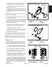
E. Remove two (2) socket head screws (item 11)
that secure pivot hub to cutting unit side plate.
F. Remove pivot hub with attached idler plate as-
sembly from cutting unit.
G. Support groomer shaft to prevent it from falling.
Carefully slide drive side groomer plate from groom-
er shaft and cutting unit. Remove groomer shim
(item 15).
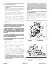
3. Carefully pull the groomer reel from the non- drive
side groomer p late assembly.
4. To remove groomer plate (item 18) from groomer
non- drive side of cutting unit:
A. Remove shoulder bolt (item 20) that secures
quick- up ball joint rod to non- drive side groomer
plate. Locate and retrieve spacer from between ball
joint rod and groomer plate.
B. Remove two (2) socket head screws (item 11)
that secure pivot hub to cutting unit side plate.
C. Remove pivot hub from cutting unit.
D. Support groomer shaft to prevent it from falling.
Carefully slide non- drive side groomer plate from
groomer shaft and cutting unit.
5. Inspect seals, bearings and bushings in groomer
plates. Remove and discard damaged components.
NOTE: See Groomer Reel Service in this section for in-
formation about groomer reel disassembly and assem-
bly.
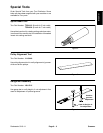
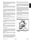
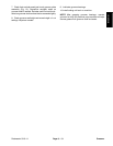
Installation (Fig. 8)
1. If seals, bearings or bushing was removed from ei-
ther of the groomer plates, install new components not-
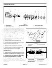
ing proper orientation as shown in Figures 9, 10 and 11.
A. Press bushing into groomer plate until the bush-
ing contacts the shoulder in the groomer plate bore.
B. Pack bearings with grease before installation.
C. Press bearings into groomer plate so that bear-
ings contact shoulder in groomer plate bore.
D. Install grease seals so that seal lips are posi-
tioned toward the groomer blade location. Seals
should be flush with surface of groomer plate.
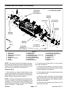
E. If groomer studs were removed from drive side
groomer plate and studs are being reinstalled, apply
Loctite #242 (or equivalent) to threads of studs. New
studs have patchlock on threads. Install studs into
groomer plate and torque from 14 to 18 ft- lb (19 to
24 N- m).
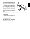
1. Groomer plate
2. Bushing
3. Seal
4. Bearing
5. Groomer stud
6. Grease fitting
Figure 9
1
2
3
4
5
6
3
14 to 18 ft-lb
(19 to 24 N-m)
DRIVE SIDE GROOMER PLATE
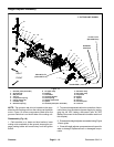
1. Groomer plate
2. Bushing
3. Seal
4. Bearing
5. Grease fitting
Figure 10
1
2
3
4
5
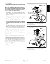
NON-DRIVE SIDE GROOMER PLATE
1. Drive side groomer plate
2. Non-drive groomer plate
3. Bearing
4. Grease seal
Figure 11
2
1
4
3
4
3
4
Groomer