


Reelmaster 5010- H Page 5 - 45 Electrical System
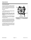
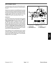
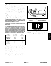
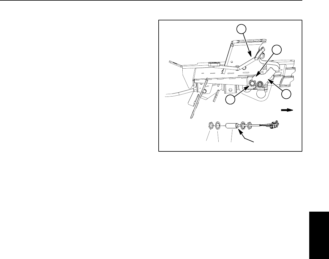
Mow/Transport Switch
The mow/transportswitch isa normally closedproximity
switch that is attached tothe bottom of the floorplatform
(Fig. 30).
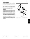
When themowstopleveris in theMOW position, thetab
on themow stoplever ispositioned awayfrom thetarget
end of the m ow/transport switch so the switch is closed.
Thetab onthemow stoplever ismovednext tothe mow/
transport switch when the mow stop lever is in the
TRANSPORTpositioncausingtheswitchtoopen.
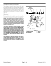
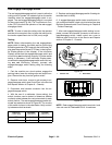
Adjustment
The distance between them ow/transport switchand the
tab on the mow stop lever should be from 0.094” to
0.100”(2.4 to2.5 mm)whenthe mowstop leveris inthe
TRANSPORT position. If distance is incorrect, loosen
jam nuts that secure brake switch to frame bracket.
Position switch with jam nuts to allow correct clearance
betweenswitch andmow stoplever.Jam nuts shouldbe
torqued from 162to 198 in-lb (18.4 to 22.4 N- m).After
jam nuts a re tightened, make sure that clearance has
not changed a nd that mow stop lever does not contact
switch as it is moved between positions.
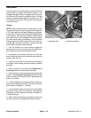
After adjustment to the mow/transport switch, use the
InfoCenter Display to verify that mow/transport switch
and circuit wiring are functioning c orrectly (see Diag-
nostics Screen (Hi/Low Range item) in the InfoCenter
Display section of this chapter).
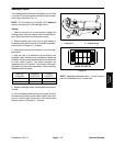
1. Traction pedal
2. Mow stop lever
3. Mow/transport switch
4. Lever tab
5. Lock washer (2 used)
6. Jam nut (2 used)
Figure 30
2
1
3
FRONT
LED location
3
6
5
4
Electrical
System